In this post, we will understand the types of DC injection braking and their uses in a VFD (variable frequency drive).
When using an AC induction motor with VFD, braking is a very important factor for using the motor efficiently. A lot depends on it and also decides the total amount of energy that the motor will dissipate and use.
VFD Braking Techniques
The four most commonly used braking techniques in a motor are
- Coast to stop,
- Ramp to stop,
- Regenerative braking and
- Dynamic braking.
Coast to Stop
Coast to stop means disconnecting the motor from the VFD output power supply.
This allows the motor to stop itself in a certain span of time; or you can say, just freeing the motor from the operation.
Ramp to Stop
Ramp to stop means applying deceleration time to the motor (ramp-down time set in VFD) to stop the motor in that time.
The motor is not disconnected at all in the ramp to stop.
Regenerative Braking
In regenerative braking, energy is generated back into the DC bus capacitors.
This method can stop the motor quickly in applications where the inertia is small or there is a significant friction load.
But, if the load inertia is very high, a large amount of energy will be generated in the capacitors and cause over-voltage.
Though the VFDs have a limit in overvoltage, exceeding the limit will generate a fault and trip the VFD.
Dynamic Braking
Dynamic braking is an extension of regenerative braking. When the voltage exceeds the limit, a dynamic braking resistor which is used across the bus will dissipate the extra energy in it. But, it increases the size of the system and also the complexity.
So, for high inertia loads, working at a high speed with them and using these methods for braking can cause some level of instability; as they will take more time to stop due to natural forces and can damage the nearby environment.
This causes the need to use DC injection braking for high inertia loads with rapid and safe stop action.
DC Injection Braking
Let us consider a simple theory for understanding this. An AC induction motor moves by a rotating magnetic field generated by the AC supply voltage. This field is induced in the rotor and causes rotation and torque at the motor shaft. When the voltage is removed, the motor will stop.
Now, going into our part; as we saw, if we induce a fixed magnetic field around the stator, then the motor stops. This can also be achieved by DC Injection braking.
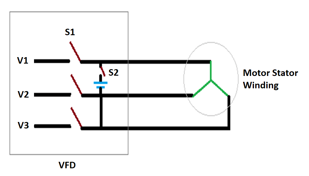
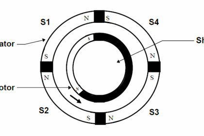
DC injection is a method of applying DC (fixed) voltage in the stator windings. Refer to the below image for the study. In running condition, the S1 switch will be closed to supply alternating AC voltage to the windings.
When the stop command is given from VFD, the S1 switch will open first; and then after a delay, the S2 switch will close. This will apply fixed DC voltage in the windings.
Due to fixed potential, a fixed magnetic field will be developed around the windings and will stop the rotor motion immediately; due to the immediate application of high braking torque.
The amount of torque applied depends on the amount of voltage and current applied at the windings.
The switch control is precisely happened inside the VFD to avoid unwanted sparks or short circuit.
Uses of Braking
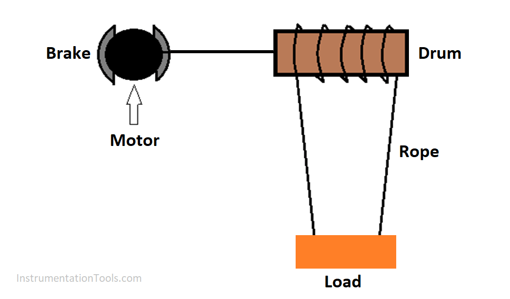
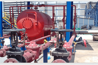
Consider another use of DC injection braking in the below image of a hoist system.
Suppose the system is in off condition and the hoist is at an upper level; holding the load. The brake is a mechanical device that is energized electrically to hold the motor tightly.
Now, if the brake fails electrically, the brake will not be able to hold the motor then and will thus indirectly release the hoist load. This can be imagined on how it can damage the environment or nearby personnel.
In stop condition, the load is moving and it can harm the system.
Also Read: Braking Theory in VFD
This can be overcome by DC injection braking. As you know, an encoder can be mounted with the motor side.
Connect the encoder to the VFD and program it in such a way that, when the VFD senses encoder counts in stop condition, DC injection braking logic will be activated.
So, as soon as the motor starts moving in stop condition, the VFD will start this braking and hold the motor immediately by inducing a high DC current.
But, remember that do not overtime this braking. A high amount of this braking can dissipate a large amount of heat in this system and cause damage.
So, generate an external alarm through VFD and alert the operators to come and check the system. They will immediately take action and bring the system to a safe state.
DC injection can be stopped either by a fixed time in the VFD or by power recycling the VFD.
So, DC injection is of great use for high-inertia and load motors. They can immediately stop the motor and bring the system to a safe operating condition.
If you liked this article, then please subscribe to our YouTube Channel for Instrumentation, Electrical, PLC and SCADA video tutorials.
You can also follow us on Facebook and Twitter to receive daily updates.
Read Next:
- Basic of a Safety Relay
- Analog and Digital Signals
- Building Management System
- Control Multiple Motors with VFD
- Isolators & Barriers in Electrical Panel


I have installed an A800 VFD inverter and entered all the parameters that were in the A700 fault VFD ,But what is happening is that;since we are using the drive on an automatic wire winding machine,when i start winding ,it is running and counting up to 45Hz instead of 50Hz but when the machine stops automatically with respect to encoder via external brake on the machine the keeps on rotating until a certain period that is when it stops.what parameters can i work on?I have tried to change values in Pr7-Pr 12 but nothing seems to change.may be am not accurate on values.