In a previous article, we gave a simple introduction to the concept of Distributed IO devices, what are they, and why we need them.
In this article, we will show how to configure a distributed IO device in our PLC project. As usual, we are focused on the Siemens and TIA Portal systems, so we will show that using Siemens ET200S distributed IO.
Contents:
- Hardware Configuration of Distributed IO Devices.
- Assign the IO module to a controller.
- Download the Configuration to the actual hardware Module.
Hardware Configuration of Distributed IO Devices
The hardware configuration of any Distributed IO device simply means assigning that IO device to a certain controller in your project, so that the Input signal from this IO will go to that PLC and the output command will come from that PLC.
Let’s add a PLC to our project and see how we can proceed. See picture 1.
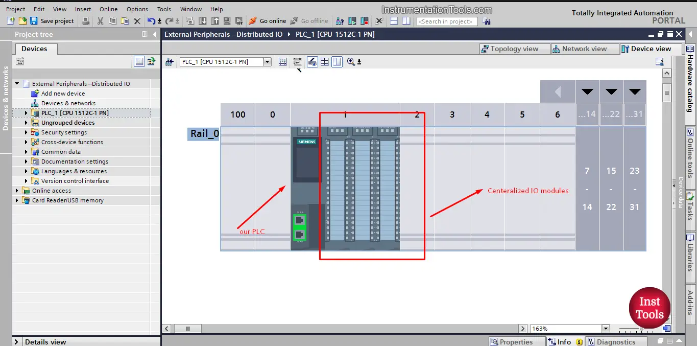
picture 1. Add PLC to our project.
As you can from the PLC we just added, the PLC already has some centralized IOs, but in this article, we assume that we have a part of the machine that is far away and I need to connect to the PLC, in that case, we would use a Distributed IO device that will be installed at the machine part and it will have all the IOs related to that part of the machine and the Distributed IO device will then communicate with the PLC via a suitable type of communication method like Profinet or Profibus.
Distributed IO in a PLC Project
Let’s add our ET200S device. See picture 2.
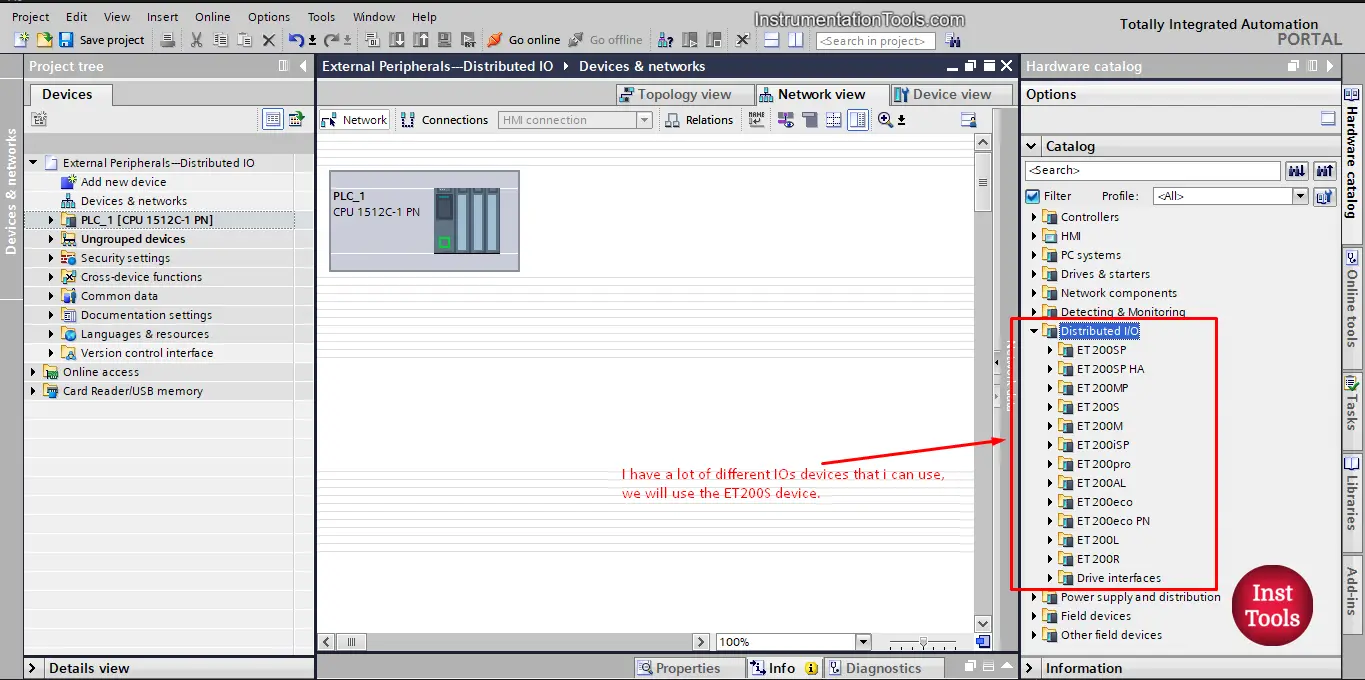
picture 2. Add the IO module you need.
As you can see from the picture, there are a lot of different IO modules you can choose from depending on your application.
We will choose the standard ET200S module. See picture 3.
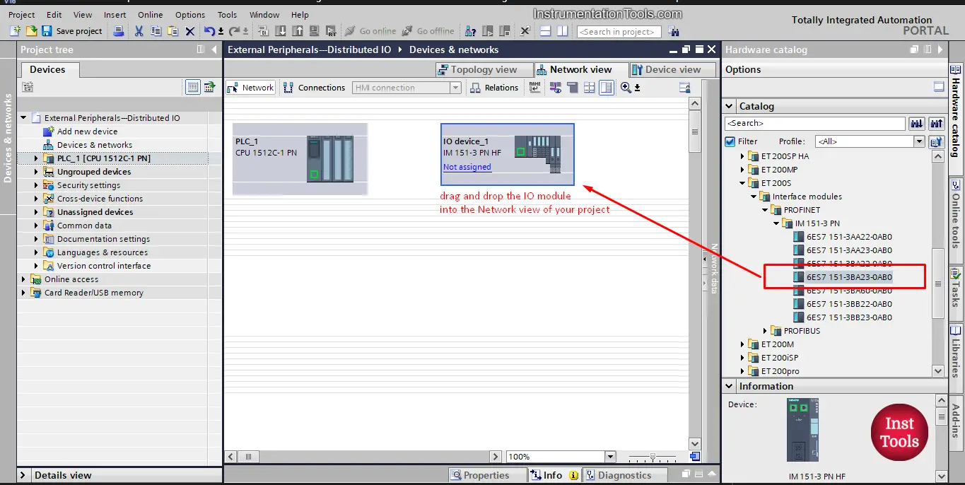
picture 3. Drag and drop the ET200s module
As you can see from the picture, just drag and drop the IO module into the Network view of your project. Note that we choose the Profinet interface for the IO module to be the same as our PLC.
After adding the ET200S module to our project we can start adding our inputs and outputs modules to the ET200S, you can find all the IOs compatible with the chosen module from the hardware catalog bar on the right, see picture 4.
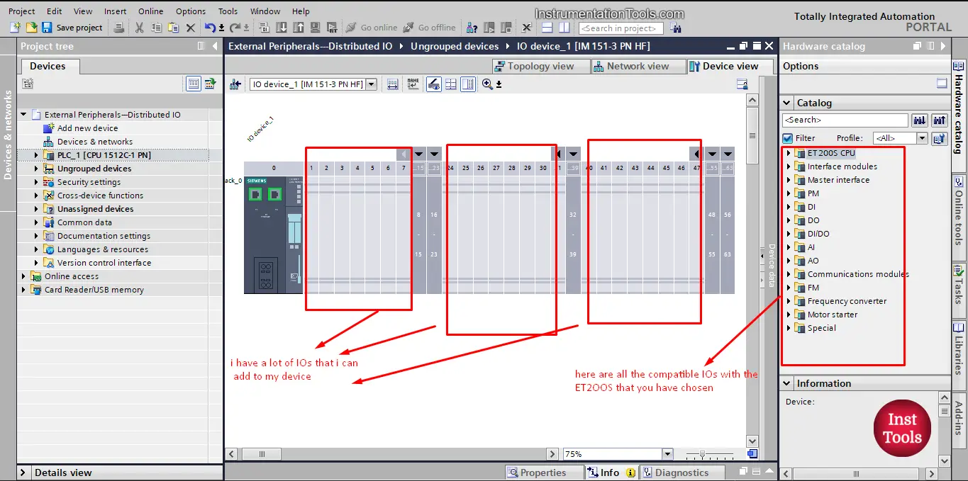
picture 4. Add the IOs to the ET200S.
As you can see from the picture, I can add the IOs by dragging and dropping them to the empty areas. The maximum number of IOs I can use with the ET200S depends on the type and specification of it.
To add your inputs and outputs modules, just drag it and drop it from the hardware catalog on the right, see picture 5.
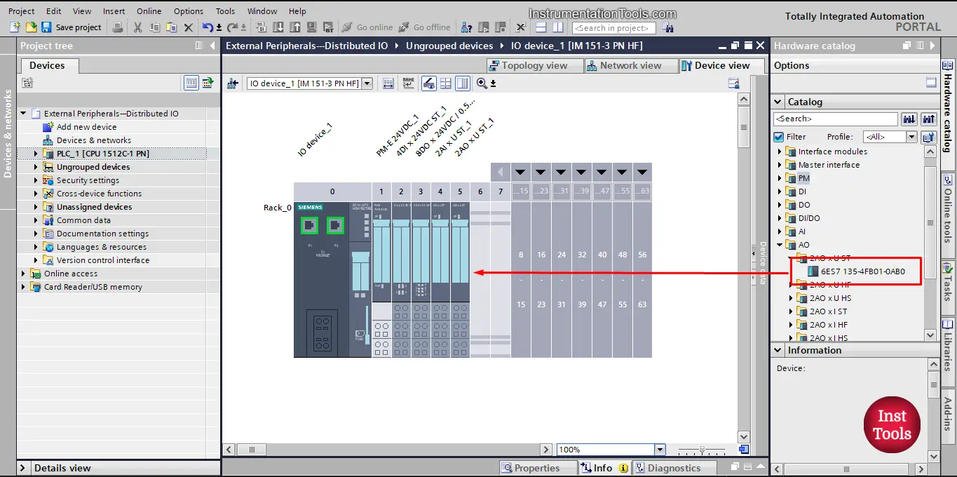
picture 5. Drag and drop the IOs you need.
Assign the IO module to a controller
Now, that you added the Distributed IO module to your project, you will notice that the IO device is not assigned or connected to any Controllers. See picture 6.
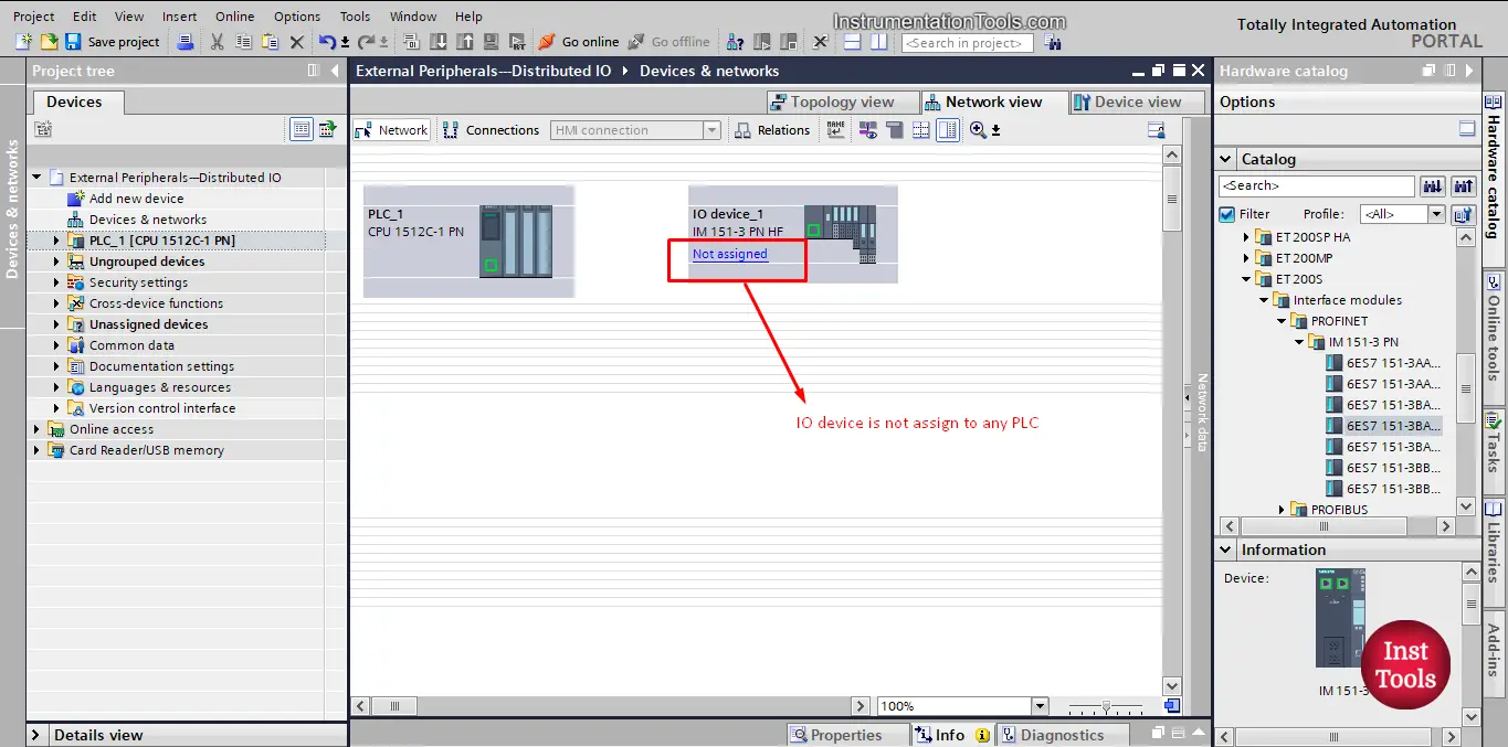
Picture 6. The added IO module is not assigned to PLC.
Another way to see that the Distributed IO module is not assigned to any controllers is that there are no addresses assigned to my IOs. As it is not connected to any controllers, see picture 7.
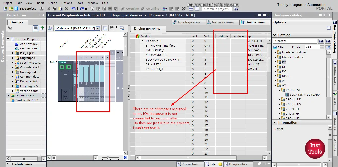
picture 7. Addresses are not defined.
As you can see in the picture, there I and O addresses area are blank, indicating they are yet to be assigned to a controller. So we need to assign the IO module to a PLC.
To assign the IO module to a controller, we need to go to Network view, select the IO module, then right click and press the “Assign to new DP master/IO controller”, see picture 8.
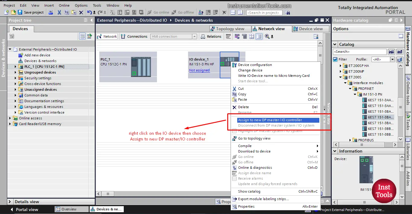
picture 8. Assign the IO module to a controller.
After you press the “Assign to new DP master/IO controller”, the select IO controller window will appear, where you can choose the PLC you want to assign the IO module to, in our project we only have one controller, so the window will show only one option. See picture 9.
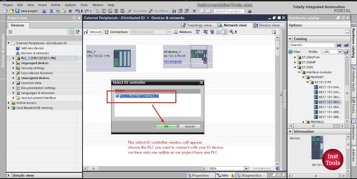
picture 9. Select IO controller window.
Once you press OK, the IO module will be assigned to the PLC. And now, if you check the device view of the IO module, you will find the inputs and outputs now have been assigned addresses in the project, which means they are now belong to a certain PLC controller. See picture 10.
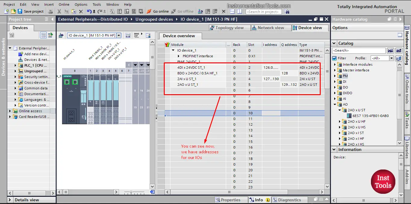
Picture 10. IO module now have assigned addresses.
Download the Configuration to the actual hardware Module
And that is how you can select and configure a distributed IO module and assigned it to a PLC in your project.
However, there is something that you should know,
YES, we did assigned our IO module to the PLC, but that was only done in the software side (TIA Portal). The actual Hardware IO device still doesn’t know it is assigned to that PLC.
That means If I downloaded my project to the PLC it will be complied and downloaded successfully, but when the PLC need to contact with the IO device to get an input or give an output command it won’t be able to find the device, even though there is a communication cable between the two. And an error will be given by the PLC.
To solve this, I have to do something called “ASSIGN DEVICE NAME”
To do that, just right click on the IO device and press assign device name, this will open the following window, see picture 11.
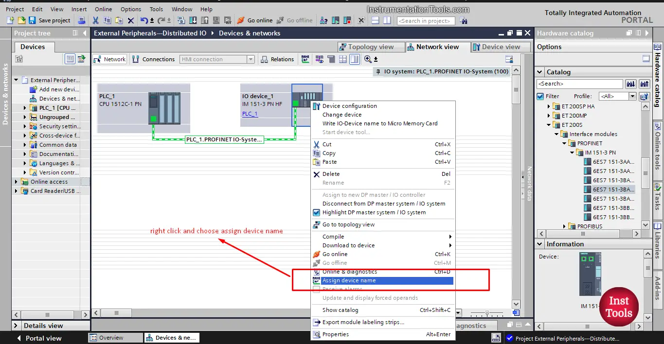
picture 11. Assign device name.
When you click the assign device name the “assign PROFINET device name” window will appear. See picture 12.
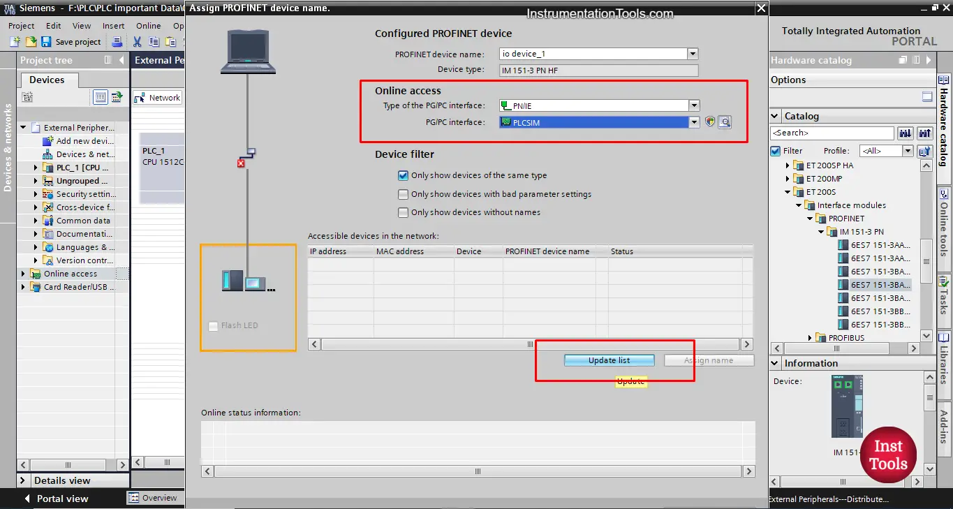
picture 12. Assign device name window.
This procedure is done with hardware devices, but as we don’t have the hardware component and only simulating we can’t see it here.
But, simply when you choose the PC/PG interface and click update you should find your IO device, then you just choose assign device name to assign the device name to the actual IO hardware module.
Once that is done, you can now use this IO device as a normal IO of the PLC. And you can find the IO module inside the PLC project tree because now it is part of the PLC. See picture 13.
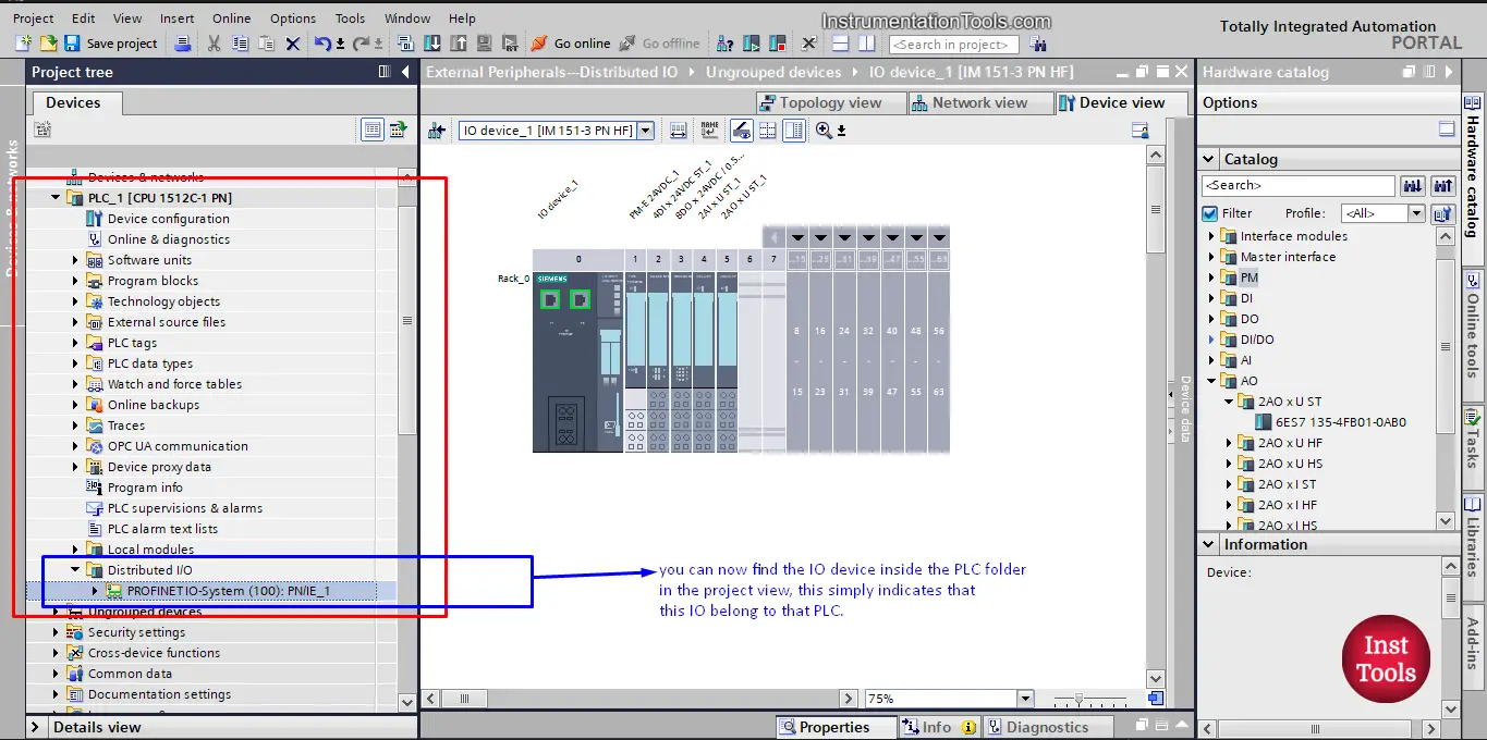
Picture 13. The IO module belongs to PLC project tree.
If you liked this article, then please subscribe to our YouTube Channel for Instrumentation, Electrical, PLC, and SCADA video tutorials.
You can also follow us on Facebook and Twitter to receive daily updates.
Read Next:
- How to Create a Faceplate?
- Difference between PLC and PAC
- Power Supply Sizing for Systems
- How to Read the PLC Datasheet?
- S7-1200 Hardware Configuration