Inst ToolsInst ToolsInst Tools
  • Courses
  • Automation
    • PLC
    • Control System
    • Safety System
    • Communication
    • Fire & Gas System
  • Instrumentation
    • Design
    • Pressure
    • Temperature
    • Flow
    • Level
    • Vibration
    • Analyzer
    • Control Valve
    • Switch
    • Calibration
    • Erection & Commissioning
  • Interview
    • Instrumentation
    • Electrical
    • Electronics
    • Practical
  • Q&A
    • Instrumentation
    • Control System
    • Electrical
    • Electronics
    • Analog Electronics
    • Digital Electronics
    • Power Electronics
    • Microprocessor
  • Request
Search
  • Books
  • Software
  • Projects
  • Process
  • Tools
  • Basics
  • Formula
  • Power Plant
  • Root Cause Analysis
  • Electrical Basics
  • Animation
  • Standards
  • 4-20 mA Course
  • Siemens PLC Course
Reading: PLC Automatic Pedal Switch for Speed Control
Share
Notification Show More
Font ResizerAa
Inst ToolsInst Tools
Font ResizerAa
  • Courses
  • Design
  • PLC
  • Interview
  • Control System
Search
  • Courses
  • Automation
    • PLC
    • Control System
    • Safety System
    • Communication
    • Fire & Gas System
  • Instrumentation
    • Design
    • Pressure
    • Temperature
    • Flow
    • Level
    • Vibration
    • Analyzer
    • Control Valve
    • Switch
    • Calibration
    • Erection & Commissioning
  • Interview
    • Instrumentation
    • Electrical
    • Electronics
    • Practical
  • Q&A
    • Instrumentation
    • Control System
    • Electrical
    • Electronics
    • Analog Electronics
    • Digital Electronics
    • Power Electronics
    • Microprocessor
  • Request
Follow US
All rights reserved. Reproduction in whole or in part without written permission is prohibited.
Inst Tools > Blog > PLC Tutorials > PLC Automatic Pedal Switch for Speed Control

PLC Automatic Pedal Switch for Speed Control

Last updated: March 4, 2021 3:51 pm
Editorial Staff
PLC Tutorials
No Comments
Share
3 Min Read
SHARE

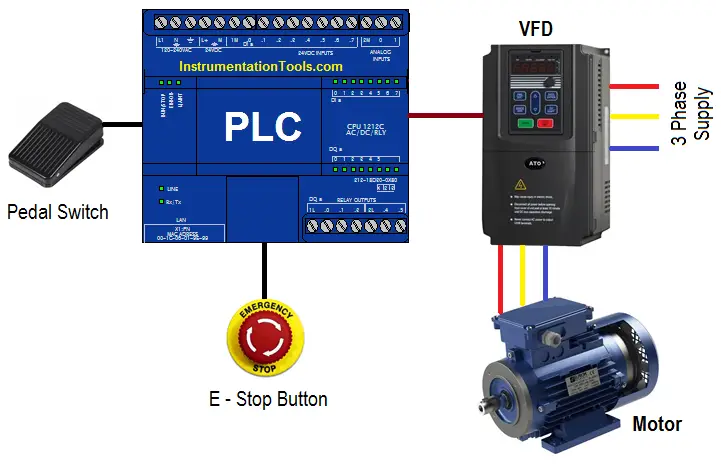
We need to use pedal switch control logic at machine work shop for speed control of motor. Write the PLC program for this application using ladder diagram.

Contents
Pedal Switch for Speed ControlPLC SolutionList of Inputs/OutputsPLC Logic Automatic pedal switch for Speed ControlLadder Logic Description

Pedal Switch for Speed Control

PLC Automatic Pedal Switch for Speed Control

PLC Solution

Here we want to operate machine in two different speeds. For this control, we are using pedal switch so we can control the speed of motor.

For normal operation we need to operate machine in speed 1 condition. And for higher operation we need to operate machine in speed 2.

Here we have considered two different speeds of motor. so, by pressing pedal switch first time motor can be started at speed 1. When user will press pedal switch again motor will run at speed 2.

Motor can be stopped by pressing E stop button.

List of Inputs/Outputs

List of Inputs

  • I1 : Pedal switch
  • I2 : E stop button

List of Outputs

  • Q1 : Speed 1
  • Q2 : Speed 2

PLC Logic Automatic pedal switch for Speed Control
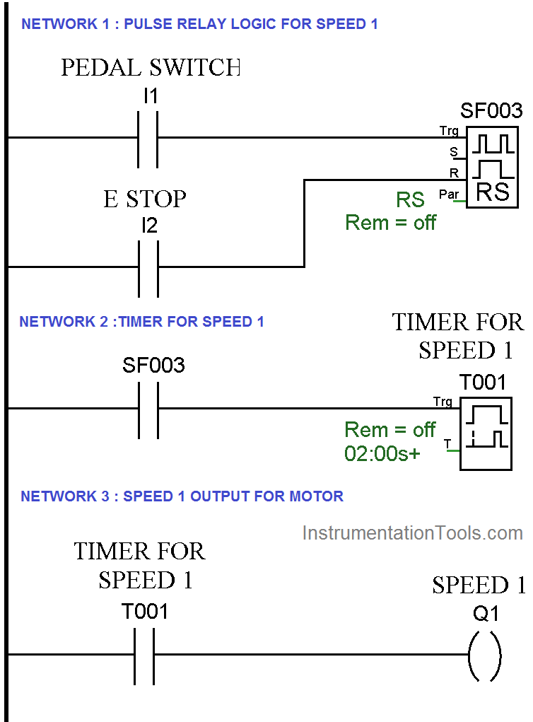
PLC Pedal Switch Logic for Speed Control
PLC Switch Ladder Diagram

Ladder Logic Description

Network 1 :-

In this network, we have used pulse relay instruction for speed 1 output.

Network 2 :-

When pedal switch is triggered first time, it will operate on delay timer.

Network 3 :-

After some 2s delay motor will run at first speed.

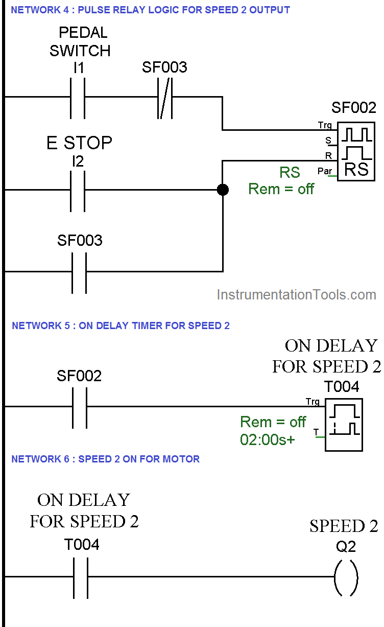
Network 4 :-

In this network we have used another pulse relay instruction for the speed 2 output.

Network 5 :-

When pedal switch is triggered second time, it will operate on delay timer for the speed 2.

Network 6 :-

When timer is completed, motor will run at speed 2.

Note:- Above application may be different from actual application. This example is only for explanation purpose only. We can implement this logic in other PLC also. This is the simple automatic pedal switch for speed selection using PLC, we can use this concept in other examples also.

All parameters and graphical representations considered in this example are for explanation purpose only, parameters or representation may be different in actual applications. Also all interlocks are not considered in the application.

Author : Bhavesh

If you liked this article, then please subscribe to our YouTube Channel for PLC and SCADA video tutorials.

You can also follow us on Facebook and Twitter to receive daily updates.

Read Next:

Variable Frequency Drive (VFD)
Types of AC and DC Motors

Stepper Motor Principle

Electrical Drives Questions

PLC Pump Control Video

Don't Miss Our Updates
Be the first to get exclusive content straight to your email.
We promise not to spam you. You can unsubscribe at any time.
Invalid email address
You've successfully subscribed !

Continue Reading

D Flip Flop PLC Ladder Logic
Top PLC Manufacturers
Oil and Water Separation Process using PLC Programming
Upload Option Disabled in Siemens PLC
#17 PLC Best Practices – Log PLC Uptime and Trend it on HMI
One Shot Rising PLC Example Program
Share This Article
Facebook Whatsapp Whatsapp LinkedIn Copy Link
Share
Leave a Comment

Leave a Reply Cancel reply

Your email address will not be published. Required fields are marked *

Stay Connected

128.3kFollowersLike
69.1kFollowersFollow
210kSubscribersSubscribe
38kFollowersFollow

Categories

Explore More

PLC Analog Signals Wiring Techniques
PLC Scan Time
Allen Bradley PLC Subroutines
PLC Packing Machine Control System Program in XG5000
What is a Data Block? Global Data Blocks in PLC
Traffic Light Control using PLC Ladder Logic
Safety Considerations in PLC System Design
Types of PLC Memory

Keep Learning

Sinking and Sourcing Devices Operation

PLC Sinking and Sourcing Explanation

Functional Block Diagram of XNOR Logic Gate

PLC Functional Block Diagram for Logic Gates

Basics of Sinking and Sourcing

Basics of Sinking and Sourcing – Automation System MCQ

PLC Memory Organization - Data Files and Program Files

PLC Memory Organization – Data Files and Program Files

Jog button in Motor Start Stop Logic using PLC

Jog Function in Motor Start Stop Logic using PLC

PLC Program for Selective Execution of the Application

PLC Selective Execution of the Application – Example Program

Control Speed of an Induction Motor using Analog Output of PLC

Control Speed of Induction Motor using Analog Output of PLC

Simulator in S7-1200 and S7-1500 PLC

How to Work With Simulator in S7-1200 and S7-1500 PLC?

Learn More

Career Scope in Electronics Engineering

Career Scope in Electronics Engineering

PLC Scan Time

PLC Scan Time

Electric Circuits Objective Questions

Electric Circuits Objective Questions – Set 8

Infrastructure Monitoring in Your Business Operations

Infrastructure Monitoring in Your Business Operations

Synchronous Motor Working Principle

Moisture Calculator

Moisture Calculator

Basic Power Electronics Interview Questions

Basic Power Electronics Interview Questions

What is a Dosing Pump? - Types, Advantages, Applications

What is a Dosing Pump? – Types, Advantages, Applications

Menu

  • About
  • Privacy Policy
  • Copyright

Quick Links

  • Learn PLC
  • Helping Hand
  • Part Time Job

YouTube Subscribe

Follow US
All rights reserved. Reproduction in whole or in part without written permission is prohibited.
Welcome Back!

Sign in to your account

Username or Email Address
Password

Lost your password?