Inst ToolsInst ToolsInst Tools
  • Courses
  • Videos
  • Q & A
    • Interview
      • Instrumentation
      • Electronics
      • Electrical
      • Practical Questions
    • MCQ
      • Instrumentation MCQ
      • Electrical MCQ
      • Electronics MCQ
      • Control Systems MCQ
      • Analog Electronics MCQ
      • Digital Electronics MCQ
      • Power Electronics MCQ
      • Microprocessor MCQ
      • Multiple Choice Questions
  • EE
    • Electronics
      • Electronics Q & A
      • Electronic Basics
      • Electronic Devices & Circuits
      • Electronics Animation
      • Digital Electronics
    • Electrical
      • Electrical Basics
      • Electrical Q & A
      • Power Electronics
      • Electrical Machines
      • Electrical Animation
      • Power Systems
      • Switchgear & Protection
      • Transmission & Distribution
  • Measure
    • Control Valves
    • Calibration
    • Temperature
    • Pressure
    • Flow
    • Level
    • Analyzers
    • Switches
    • Vibration
    • Solenoid Valve
  • Control
    • PLC Tutorials
    • Control Systems
    • Safety Instrumented System (SIS)
    • Communication
    • Fire & Gas System
  • More
    • Design
    • Tools
    • Animation
    • Basics
    • Formulas
    • Standards
    • TextBooks
    • Common
    • Software
    • Excel Tools
    • Erection & Commissioning
    • Process Fundamentals
    • Videos
    • Books
Search
All rights reserved. Reproduction in whole or in part without written permission is prohibited.
Reading: Why 4-20 mA Current Signal is used instead of Voltage Signal?
Share
Notification Show More
Font ResizerAa
Inst ToolsInst Tools
Font ResizerAa
  • Courses
  • PLC Tutorials
  • Control Systems
Search
  • Courses
  • Videos
  • Q & A
    • Interview
    • MCQ
  • EE
    • Electronics
    • Electrical
  • Measure
    • Control Valves
    • Calibration
    • Temperature
    • Pressure
    • Flow
    • Level
    • Analyzers
    • Switches
    • Vibration
    • Solenoid Valve
  • Control
    • PLC Tutorials
    • Control Systems
    • Safety Instrumented System (SIS)
    • Communication
    • Fire & Gas System
  • More
    • Design
    • Tools
    • Animation
    • Basics
    • Formulas
    • Standards
    • TextBooks
    • Common
    • Software
    • Excel Tools
    • Erection & Commissioning
    • Process Fundamentals
    • Videos
    • Books
Follow US
All rights reserved. Reproduction in whole or in part without written permission is prohibited.
Inst Tools > Blog > Basics > Why 4-20 mA Current Signal is used instead of Voltage Signal?

Why 4-20 mA Current Signal is used instead of Voltage Signal?

Learn why 4-20 mA current signal is used in industrial automation plants instead of a voltage signal 0-5v, 0-10v etc.

Last updated: March 16, 2021 9:35 am
Editorial Staff
Basics Control Systems
8 Comments
Share
4 Min Read
SHARE

Voltage Signal

The electrical signals can be transmitted in two different ways.

Contents
Voltage SignalCurrent SignalWhy 4-20 mA Current Signal?
  1. Current signal and
  2. Voltage signal.

The voltage signal when transmitted over a long distance it causes a voltage drop in the wires.

There might be large voltage difference between the sending end and receiving end. This leads to measurement errors as our process variable reading present in the voltage form.

Thus, voltage signal is generally not used because of more error in measurement.

Current Signal

On the other hand, the current signal does not get affected with voltage drop in the loop wires. The measuring accuracy of the current signal transmission is far better than voltage transmission signal.

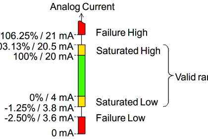
The transmitter manufactured for automation purpose can output 0-20mA or 4-20 mA signal.

The 4-20 mA signal is preferred over 0-20 mA signal because the broken wire can be easily detected with use of 4-20 mA signal.

If current observed is zero in a 4-20 mA transmitter, the transmitter will output an error signal.

The current signal can be transmitted without error to a distance of 1000 meters.

Why 4-20 mA Current Signal?

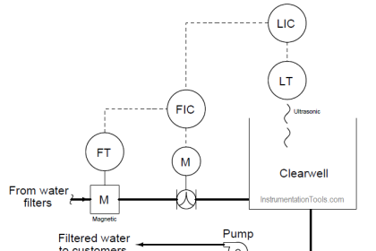
The transmitter is generally loop powered with 24 volts supply. The transmitter with this arrangement is called 2 wire transmitter.

The process signal can be measured by connecting ampere meter in the series with the 24 volts supply source.

The response of current signal is more linear than the response of voltage signal, and therefore, current signal is preferred over voltage signal.

why 4-20 ma is used instead of 0-10v

It is desired that the signal must be reproduced at the control system end exactly what was produced at the transmitter end so that both sides read and display the same values.

The signal should not interfere with the external electromagnetic interference or electrostatic interference. If these external signals superimposed on the measuring signal it can cause substantial error in the measurement.

The noise immunity of the current signal and voltage signal depends on the impedance of the source. The current signal provides low impedance to sensor/transmitter in comparison to voltage source, and the thus current signal has better immunity to noise.

4-20 mA current signal is safe for hazardous area because of low power, and there is no risk of electric shock or fire.

The 4-20 mA signal is fed in the 250 ohms resistance connected to the transmitter circuit.

The resistor converts the current signal into a voltage signal for onward conversion in digital signal through an analog to digital converter which is located in the analog input module of PLC or DCS system cabinets.

Author: Satyadeo Vyas

If you liked this article, then please subscribe to our YouTube Channel for PLC and SCADA video tutorials.

You can also follow us on Facebook and Twitter to receive daily updates.

Read Next:

  • Basics of Loop Checks
  • 4 to 20 mA Calculations
  • Advantages of 4 to 20 mA
  • Measurement of Errors Questions
  • Sensors and Transducers Classification
Don't Miss Our Updates
Be the first to get exclusive content straight to your email.
We promise not to spam you. You can unsubscribe at any time.
Invalid email address
You've successfully subscribed !

Continue Reading

Performance Characteristics of Sensors and Transducers
Runaway Processes
How to Do Loop Checks During Plant Pre-Commissioning
Instrument Errors – Zero, Span, Linearity
Electrical Earthing Calculations
Notes on Instrument Ranging
Share This Article
Facebook Whatsapp Whatsapp LinkedIn Copy Link
Share
8 Comments
  • Jassem Akeed says:
    May 14, 2021 at 10:39 am

    intrested subject

    Reply
    • krushna Mohanta says:
      May 15, 2021 at 2:27 pm

      Yes

      Reply
    • AJAY MISHRA says:
      January 2, 2023 at 12:17 pm

      The voltage signal when transmitted over a long distance it causes a voltage drop in the wires.

      Reply
  • Garth says:
    October 6, 2022 at 9:13 am

    Sensible description.

    Reply
  • Marcilio Antonio Viana Pongitori says:
    March 13, 2023 at 4:31 pm

    Publicação correta e muito bem colocada

    Reply
  • Mario Sanchez says:
    March 13, 2023 at 11:33 pm

    Really interesting topic thanks!
    I would add that with IO-Link Sensors you can get more in an easier way.
    You get the value (so you do not need to translate voltage or current into the value), you get the status of the device, and the replacement is plug&play as IO-Link master transfers the settings to the sensor automatically, even identifying the possible model errors.

    Reply
  • James says:
    March 14, 2023 at 9:30 pm

    I understand the concept of voltage drop but what about the 24V power? Would this not degrade over a long distance, therefore affecting the current?

    Reply
    • Nic says:
      March 16, 2023 at 8:31 pm

      Voltage, Current, and Resistance are related by the equation V = IR, where V is voltage, I is current, and R is resistance. Every cable has a little bit of resistance built in, and for short runs, its is normally small enough to not cause much error. However, as the cable gets longer (1000 meters), this resistance is magnified, and thus, produces a larger error. What the instrument hopes to do in a loop between the power supply and the sensing element of the Input card is to adjust the voltage or current. However, when using voltage, the instrument cannot adjust for resistance that it doesn’t know about. For example, let’s say we have this wiring diagram:
      Power R1 (Cable) (0-10V) R2 (Cable) (R3 – Fixed Internal)
      +24V —— /\/\/\/\ —— Instrument —– /\/\/\/\ —— Input ————– 0V

      In this diagram, the voltage seen by the Input has a voltage drop equal to the voltage set by the instrument, dropped by an amount the resistance creates from the current flowing through it.

      The equation would be: Vinput = (Vinstrument * R3) / (R2 + R3)

      If the Instrument output 10V, the Resistance of R2 was 1 Ohm, and R3 was 1 Ohm, the instrument would see is (10*1)/(1+1) = 10/2 = 5V. This is an exaggeration of resistance, but you get the point. However, what is common on all of these resistors in the loop is the current. It is the same across all devices, and is basically V / R = 10 / ( 1 +1 ) = 5. If the instrument can control the current, then the current will be seen by everyone the same.

      Look up Kirchhoff’s Voltage Law if you want more information on this. Current Loops and Voltage Dividers are what is happening here.

      I hope that makes sense.

      Reply

Leave a Reply Cancel reply

Your email address will not be published. Required fields are marked *

Stay Connected

128.3kFollowersLike
69.1kFollowersFollow
208kSubscribersSubscribe
38kFollowersFollow

Categories

Explore More

PID Controller Loop Tuning Questions and Answers – Part 2
Comparison of Proportional Integral Derivative Controllers (PID)
Process Control Loop Testing
Best Way to Build Troubleshooting Mindset for Automation Engineer
Remote Factory Acceptance Test
Questions on Ratio Control System
What is Static Grounding?
Definitions of Electrical Grounding

Keep Learning

Shielded Cables

The Idea Behind Shielded Cables

Types of Industrial Control Systems

Types of Industrial Control Systems

control of temperature in a vessel

How to Analyze PID Controller Actions

Control system architecture diagrams

Vendor Document for Project Systems Architecture

Closed Loop Control System

Types of Control Systems

LIC and FIC Controllers

What LIC and FIC Controllers will do?

Control Room Design Guidelines

Control Room Design Guidelines

Transmitters 4-20mA Current Failure Alarm Limits

Transmitters 4-20mA Current Failure Alarm Limits

Learn More

What is Directional Control Valve (DCV)?

What is Directional Control Valve (DCV)?

Continuity Testing using Multimeter

How to do Continuity Testing using Multimeter

Capacitive Time Constant for Charging Capacitor

Capacitive Time Constant

PLC Cooking Timer Example for Kitchen Automation

PLC Cooking Timer Example for Kitchen Automation

Feed forward example

What is Feedforward Control ?

Clamp meters

Clamp Meters Working Principle

BUS TIE REACTORS

Current Limiting Reactors in Power System

Advantages and Disadvantages of Slip Ring Induction Motor

Follow US
All rights reserved. Reproduction in whole or in part without written permission is prohibited.
Welcome Back!

Sign in to your account

Username or Email Address
Password

Lost your password?