Inst ToolsInst ToolsInst Tools
  • Courses
  • Automation
    • PLC
    • Control System
    • Safety System
    • Communication
    • Fire & Gas System
  • Instrumentation
    • Design
    • Pressure
    • Temperature
    • Flow
    • Level
    • Vibration
    • Analyzer
    • Control Valve
    • Switch
    • Calibration
    • Erection & Commissioning
  • Interview
    • Instrumentation
    • Electrical
    • Electronics
    • Practical
  • Q&A
    • Instrumentation
    • Control System
    • Electrical
    • Electronics
    • Analog Electronics
    • Digital Electronics
    • Power Electronics
    • Microprocessor
  • Request
Search
  • Books
  • Software
  • Projects
  • Process
  • Tools
  • Basics
  • Formula
  • Power Plant
  • Root Cause Analysis
  • Electrical Basics
  • Animation
  • Standards
  • 4-20 mA Course
  • Siemens PLC Course
Reading: Argonite Fire Suppression System Working Principle
Share
Font ResizerAa
Inst ToolsInst Tools
Font ResizerAa
  • Courses
  • Design
  • PLC
  • Interview
  • Control System
Search
  • Courses
  • Automation
    • PLC
    • Control System
    • Safety System
    • Communication
    • Fire & Gas System
  • Instrumentation
    • Design
    • Pressure
    • Temperature
    • Flow
    • Level
    • Vibration
    • Analyzer
    • Control Valve
    • Switch
    • Calibration
    • Erection & Commissioning
  • Interview
    • Instrumentation
    • Electrical
    • Electronics
    • Practical
  • Q&A
    • Instrumentation
    • Control System
    • Electrical
    • Electronics
    • Analog Electronics
    • Digital Electronics
    • Power Electronics
    • Microprocessor
  • Request
Follow US
All rights reserved. Reproduction in whole or in part without written permission is prohibited.
Inst Tools > Blog > Animation > Argonite Fire Suppression System Working Principle

Argonite Fire Suppression System Working Principle

Last updated: June 13, 2018 2:42 pm
Editorial Staff
Animation Fire & Gas System
2 Comments
Share
5 Min Read
SHARE

Argonite is a composite gas that consists of 50% Nitrogen and 50% Argon. The gas is mixed and stored under pressure. The composite is completely inactive and is not involved in the burning process.

In consequence, extinguishing the fire does not pose any risk of producing toxic fission products. The gas simply reduces the oxygen level from 20.9% down to 12.5% thus quenching the fire. Both nitrogen and argon work as oxygen-displacing elements, and

Argon is mainly added to achieve a specific gravity (almost) equal to that of ordinary air

Argonite System Animation

Argonite Fire Suppression System Animation

Argonite System Operation

  1. When any fire incident happens then the Fire/Smoke detectors will be activated. These detectors gives signal to the Fire Alarm Panel.
  2. The Fire Alarm Panel activates the Hooter and Stops the HVAC unit.
  3. Also the Fire Alarm Panel sends an Argonite Release command (CMD) to the Argonite System. Here in the animation we considered four Zones. Zone means areas or locations or rooms. Say if fire/smoke detectors are activated in Zone 4 then the Fire Panel sends Command 4. So Fire Alarm Panel can send Commands from CMD 1 to CMD 4 depending on the fire/smoke detectors activation in respective zone.
  4. Now Argonite System receives the Argonite Release command from Fire Alarm Panel. Argonite system wait for some time to release the argonite cylinders. Typically the time will be from 30 seconds to 60 seconds.
  5. Say sometimes we often receives False Fire/Smoke detectors alarm, in that case we have to Inhibit the Argonite Release command. Inhibit means Stop the action. Inhibit Push buttons generally installed nearer to Argonite system or respective Zones. Inhibit Push buttons are provided on the Argonite Panel also as shown in animation.
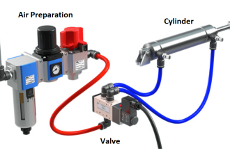
  6. Say Inhibit not given and after the time time delay, Argonite system activates the Solenoid Valve on the Master cylinder.
  7. The Master cylinder gas will be released and it has two paths to go. one is main discharge line and second will go to next slave cylinder.
  8. The Master cylinder pressure activates the Slave cylinder. Now slave cylinder also released. Similarly the Slave cylinder may also have two paths to go. one is main discharge line and second will be go to next slave cylinder. (Here in animation only one slave cylinder operation shown).
  9. Like this concept, we can release many cylinders which are connected in series by activating one master cylinder.
  10. Also as we discussed, we have Four zones or Fours areas. so we have to release the gas to the fire effected zone only. so an ON/OFF valve will be provided in the Zone 1, Zone 2, Zone 3, Zone 4 Discharge pipe lines (not shown in animation). Whenever we receive the command from Fire Alarm Panel then immediately the respective zone ON/OFF valve will be Opened immediately. Remaining valves will be in closed state. Say Command 4 is received then Zone 4 valve will be activated.
  11. Note: Generally we use more than one master cylinder either to speed up the operation or to divide the number of cylinders quantity to specific zones
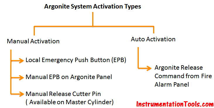
  12. A Manual valve or Release cutter pin will be provided on all Master cylinders. In case of auto failure, we can use this manual valve to release the master cylinder. Once master cylinder releases, it activates remaining slave cylinders.
  13. Emergency push buttons are also installed nearer to Argonite system or Respective zones. we can activate the argonite system by using these push buttons also. Emergency Push buttons are provided on the Argonite Panel also as shown in animation.
  14. Pressure Switches are installed in the main discharge line or specific zones also. Argonite Gas Release Indication will be taken from these Pressure Switches

Also Read : Argonite Master & Slave Cylinder Operation

Argonite System Activation Types

Benefits of the Argonite System:

  • Fast acting and effective against nearly all fire hazards
  • Environmentally neutral – zero ODP, zero GWP
  • No post-fire residues or damage to protected equipment
  • Electrically non-conductive
  • Safe for occupied areas
  • Automatic or manual release
  • Total flooding or modular design
  • Minimum downtime after a fire
Don't Miss Our Updates
Be the first to get exclusive content straight to your email.
We promise not to spam you. You can unsubscribe at any time.
Invalid email address
You've successfully subscribed !

Continue Reading

Vortex Flow meter Animation
Relay Working Animation
Four Way Solenoid Valve Working Principle
Strain Gauge Animation
Basic Guidelines for Selection of Fire and Gas Detectors
Design Basis for Fire Detection and Alarm System
Share This Article
Facebook Whatsapp Whatsapp LinkedIn Copy Link
Share
2 Comments
  • fatah says:
    August 31, 2016 at 2:01 pm

    thanks for informations, it was important for future project.

    Reply
  • IDS says:
    May 15, 2022 at 10:10 am

    Does Argonite Gas suppress Gun Power Fire?

    Reply

Leave a Reply Cancel reply

Your email address will not be published. Required fields are marked *

Stay Connected

128.3kFollowersLike
69.1kFollowersFollow
210kSubscribersSubscribe
38kFollowersFollow

Categories

Explore More

Portable Gas Detectors Calibration Procedure
Animation of Electromagnetic Relay
Interview Questions on Fire Alarm System
Gas Detectors Practical Problems and Troubleshooting
Overview of Fire/Smoke/Flame/Heat/Gas Detectors
Catalytic Type Gas Sensor Principle
PID Controller Gains Effect on Manipulated Variable
Stepper Motor Working Principle

Keep Learning

Smoke Detection System Questions

Interview Questions on Smoke Detection System

Two Wire Sensors Animation

Two Wire Sensor Working Principle and Animation

Flame Detectors Working Principle

Flame Detectors Working Principle

Vibrating Fork Level Switch Working Animation

Vibrating Fork Level Switch Working Animation

Fire Extinguishers Mock Test

Fire Extinguishers Mock Test

Sprinkler System

Basics of Sprinkler System

Gas Detection Excel Converters

Open Channel Flow Measurement Animation

Open Channel Flow Measurement Principle

Learn More

pressurized-water reactor

Runaway Processes

Electrical Machines Questions and Answers

Induction Generator Quiz

Electronic Devices & Circuits Objective Questions

Electronic Devices & Circuits Quiz – Set 3

Ratio control

What is Ratio Control ?

Top 3 Online Bachelor’s Programs in Electronics Engineering

Top 3 Online Bachelor’s Programs in Electronics Engineering

UV Visible Spectrometers Questions and Answers

UV Visible Spectrometers Questions and Answers

Hot Well Level Control System in Condensing Turbine

Hot Well Level Control System in Condensing Turbine

While Do Statement in Structured Text PLC Program

While Do Statement in Structured Text PLC Program

Menu

  • About
  • Privacy Policy
  • Copyright

Quick Links

  • Learn PLC
  • Helping Hand
  • Part Time Job

YouTube Subscribe

Follow US
All rights reserved. Reproduction in whole or in part without written permission is prohibited.
Welcome Back!

Sign in to your account

Username or Email Address
Password

Lost your password?