Alarm/Trip : Something happens—a signal peaks or falls—and you need to know. A limit alarm trip can trigger the response needed to maintain normal, and safe, operations.
A limit alarm trip monitors a process signal (such as one representing temperature, pressure, level or flow) and compares it against a preset limit. If the process signal moves to an undesirable high or low condition, the alarm activates a relay output to warn of trouble, provide on/off control or institute an emergency shutdown.
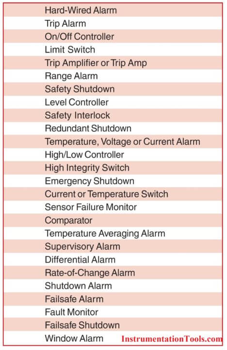
While limit alarm trips are best known as a sure way to activate a warning light, siren or bell when a process problem occurs, they are also called upon to do much more. In fact, today’s highly flexible and versatile alarm trips can be found working in a wide range of applications, under an impressive list of pseudonyms. Here are just some:
“Hard” vs. “Soft” Alarms
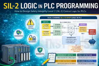
Because they are hard-wired into the process and provide relay outputs, independent limit alarm trips are often referred to as “hard” alarms. This term differentiates a “hard” alarm trip from the software-implemented alarm (a “soft” alarm) which is found within a Distributed Control System (DCS) or a programmable logic controller (PLC).
Why Use “Hard” Alarms?
Most every plant performs alarm functions using “soft” alarms within their DCS or PLC. As such, some might argue that “hard” alarms are not necessary. However, “hard” alarm trips complement DCS and PLC systems by providing redundancy, simple control and critical safeguarding.
Because of the potential consequences to plant and personnel, “hard” alarm trips continue to be the accepted industry standard for a wide range of primary alarming functions, as well as for backup of DCS and PLC strategies in critical Emergency Shutdown (ESD) and Safety Related Systems (SRS).

“Soft” alarms can be susceptible to common-mode failures (such as failure of a computer-based system’s power supply, hardware or software) that could disable all of the “soft” alarms in the entire system. Therefore, “soft” alarms may be inappropriate for providing the degree of protection demanded for some critical applications, such as those found in Emergency Shutdown Systems (ESD) or Safety Instrumented Systems (SIS).
“Hard” alarms are not exposed to the adverse effects of a common-mode failure because they maintain complete independence from the DCS or PLC (Figure 2). “Hard” alarm trips distributed throughout a facility can be used to provide warnings and safety backup measures in the event of a common-mode failure. That’s why in critical and safety-related applications, the use of “hard” alarms is a requirement of many insurance companies.

Another good reason why “hard” alarms should be considered in place of, or to back up, “soft” alarms is that rather than intermittent scanning of individual points as is accomplished by a DCS or PLC, each “hard” alarm
provides continuous supervision of an individual process signal. In some fast-changing applications, the computer’s scanning speed or network throughput time may be inadequate. In addition, “hard” alarms are typically easier to set up, which eliminates potential programming errors. They are also less prone to failure, inadvertent changes and tampering.
Basic Limit Alarm Trip Functions
Anything from simple annunciation to shut down of an entire process can be handled by a limit alarm trip. An alarm trip accepts an input signal from a monitoring or control instrument, such as a signal transmitter or sensor.
When the monitored variable falls outside of a user-set “Trip” (also called “Set”) Point, the alarm trip activates one or more of its relay outputs. The relay(s) are typically used to control a warning light, annunciator, bell, pump, motor or a shutdown system.
In most units, once an alarm trips, it remains in an alarm condition until the process signal re-crosses the trip point and passes out of the deadband. An adjustable deadband makes it possible to increase or decrease this range, thus affecting what point the relay returns to its normal, non- alarm state.
Using this relatively simple “cause and effect” action, limit alarm trips can be economically used in a wide variety of basic and complex applications:
- Warn of trouble by providing a “hard” alarm output when a process signal exceeds a high and/or low limit.
- Create an independent emergency shutdown system to aver t undesirable situations in the event of a central power failure or DCS shutdown.
- Provide redundant warning or shutdown capabilities to back-up and compensate for failure of DCS or PLC “soft” alarms.
- For simple applications, replace over-complicated PLCs with alarm trips that are easier to set up and use.
- Reliably and cost-effectively provide on/off control of pumps and motors in batching and similar applications.
- Sense dangerous conditions and shutdown control equipment before it is damaged.
- Monitor an input for a change in value, and trip an alarm when the input rate-of-change exceeds a selected rate, over a selected time period.
High and Low Limit Alarms
A high or low limit alarm is triggered when the value of the variable being measured exceeds a preset high or low alarm trip point (Figure 3).
This type of alarm trip monitors temperature, pressure, level, flow, position or status variables, and is typically used to warn of unwanted process conditions or to provide emergency shutdown.

Alarm Trips with Multiple Relay Outputs
A limit alarm trip can have one, two or even four relay outputs. Typically, each relay output can be set to respond to a different trip point. This would include any combination of high or low alarm trips, with different trip point settings for each. Some alarm trips also offer the option of setting the relay to trip if there is an input fault (such as a broken sensor), or to alert that there is a problem with the alarm trip itself (Figure 4).
The following examples describe how alarm trip points might be set for a dual output limit alarm trip. Of course, if thealarm trip had four relay outputs, any combination of these same trip options could be applied to the remaining two relays.

High Alarm
A status change (alarm condition) of a single high alarm occurs when the input rises above the trip point. The status will return to a non-alarm condition when the input falls below the deadband.
High/High Alarm
This alarm accepts one input, but has two high relays, each with its own trip point. When the input rises above Trip Point 1 (the lower trip point), the first set of contacts will change status merely to serve as a warning; however, should the input rise above Trip Point 2 (the higher trip point), the second set of contacts change status, which may initiate an emergency shutdown. With four relay outputs, you can provide three levels of warning and then an emergency shutdown (Figure 5).

Low Alarm
A status change (alarm condition) of a single low alarm occurs when the input falls below the trip point. The status will return to a non-alarm condition when the input rises above the deadband. A typical application of a low alarm is warning of a low tank level to avert problems with a pump running dry.
Low/Low Alarm
A dual low alarm accepts one input, but has two relays, each with its own independent trip point. When the input falls below Trip Point 1, the first set of contacts will change status merely to serve as a warning. Should the input fall below Trip Point 2, the second set of contacts change status, possibility initiating a shutdown of the process.
The low/low alarm’s contacts will return to a non-alarm status when the signal rises above the lowest deadband. The low alarm’s contacts return to a non-alarm status when the input signal rises above the higher alarm deadband. A typical application includes monitoring the low extreme temperature of a cryogenic tank to avoid over-cooling.
High/Low Alarm
A dual high/low alarm accepts one input and has two relays, each with a separate trip point (Figure 3).

Rate-of-Change Alarm
Used to detect changes in the measured value in units per minute or second, a rate of change alarm monitors an input for a change in value with respect to time (Figure 6). The alarm is set to trip when the input rate-of-change exceeds a user-selected rate (Delta) over a user-selected time period (Delta Time).
Input Fault Alarm
On some alarm trips, you can set one or more of the relays to trip when an input is interrupted, such as in the instance of a sensor break. This provides an alert of a non-critical sensor break without causing a costly false shutdown.
Self-Diagnostic Alarm
Some limit alarm trips continuously monitor their own status during operation, and trip if they are not operating properly.
Average and Differential Alarms
An average limit alarm trips when the average of two or three input signals exceeds a pre-selected high or low trip point (Figure 7). A differential alarm trips when the difference between two input signals, such as two RTD temperature sensors, exceeds a specific value.

Window Alarm
The Window Alarm is activated when the process variable is outside of the low/high trip point ranges (Figure 8).
On/Off Control
A limit alarm trip can also be used as a simple on/off controller such as those required in level applications (pump/valve control) when filling or emptying a container or tank (Figure 9).

Alarm Trip Relay Responses
Normally Open and Normally Closed
Normal (or normally) means the relay is in the de-energized (or shelf) state. When in the de-energized state, a normally-open (NO) relay contact does not permit current to flow to the common (C), resulting in an open circuit (Figure 10).
When the relay is energized, there is a closed circuit between the NO and the C terminal. A normally-closed (NC) relay contact allows current to flow to the common (C) when the relay is in the normal (de-energized) state (Figure 11). When the relay is energized, there is an open circuit between the NC and the C terminal (Figure 12).
There are three common types of alarm relay configurations: Single-Pole/Single-Throw; Single-Pole/ Double-Throw; and Double-Pole/Double-Throw.
Single-Pole/Single-Throw (SPST)
A SPST has one pole (Figure 10). When the contact closes, it allows current to flow across the relay. If this relay is normally- open (NO), current only flows when the contact trips (energized). If the contact is configured normally-closed (NC), current will flow until the alarm trips (energizes). The choice of Normally-Open (NO) or Normally Closed (NC) is typically selectable.

Single-Pole/Double-Throw (SPDT)
A SPDT contact has one pole and sends the electrical path in one of two directions (Figure 11). By providing both the NO and NC contacts, this type of relay can be quickly wired for any application.
Double-Pole/Double-Throw (DPDT)
These give a single alarm trip two separate outputs from one relay (Figure 12). Both contacts on a DPDT change status at the same time. A DPDT relay make it possible for an alarm trip to perform two simultaneous functions. They are commonly used to annunciate and cause an action to occur, such as shutting off a valve or starting a blower.
Failsafe and Non-Failsafe
Configuring an alarm trip as either failsafe and non- failsafe is a primary safety consideration. In a safety application, the foremost concern should be the alarm trip’s action in the case of failure. An alarm trip with a relay that de-energizes if the input signal exceeds the trip point is called failsafe (Figure 16).
This unit’s relay is energized in the normal operating condition. As a result, should the power fail, this unit’s relay operates as if it were in the alarm condition (Figure 13). Failsafe relay action is chosen for the vast majority of alarming applications.

The other relay action is non-failsafe. This unit’s relay is de-energized when the input signal is in the normal condition (Figure 15) and energized when an alarm occurs. In this configuration, the alarm trip will not provide a warning if there is a power failure (Figure 14).Should a loss of power and alarm condition coincide, the alarm would go undetected.
Normally-Open/Normally Closed Combined with Failsafe/Non-Failsafe
The characteristics of Failsafe/Non-Failsafe and Normally- Open/Normally-Closed relay action can be integrated to provide specific alarming characteristics. To illustrate, consider an application where a light needs to be turned on when a high alarm trip point is reached.
If the SPDT relay is non-failsafe, it is de-energized when in normal state (Figure 15), and energized when in alarm state. Therefore, when the trip point is exceeded, the relay energizes and sends the contact from NC to NO, turning on the light. Note that the light has to be wired to the NO side of the contact so that when the high trip occurs, the relay energizes and the circuit will close between the NO and Common (C) terminals.

If the SPDT relay is failsafe, by definition it is energized when in normal state and de-energized when in alarm state. When the trip point is exceeded, the relay de- energizes and sends the contact from NO to NC (Figure16), turning on the light by completing the circuit between the NC and C terminals.
In this configuration, the light needs to be wired to the NC side of the contact. As stated earlier, this strategy is preferred because if power to the alarm trip is lost, an alarm is initiated to warn of trouble.
Deadband
The alarm trip fires its relay at the trip point and the relay resets when the process variable reaches the deadband point. Without deadband, if the process variable was hovering and cycling above or below the trip point, the relay would be chattering on and off, leading to premature failure. By setting the deadband just one or two percent away from the trip point, you can avoid excessive relay wear (Figure 17).

A latching alarm is one where the relay cannot automatically reset. Once the relay trips, it remains in the alarm condition until an operator manually resets the relay (usually through a push button). Latching alarms are most commonly employed when you want to force an operator to acknowledge the alarm condition.
Contact Ratings and Precautions
The contact rating of relays used in alarm trips range from one to 10 amps. A typical annunciator requires only a higher amperage device, such as a pump, an interposing relay can be used. To avoid needlessly damaging relays, two precautions must be taken. First, never operate a contact higher than its rating, even if it is momentarily. The rating of the alarms trip’s relay should meet or
exceed the device it controls to insure reliable operations. Second, consider the implication of the load’s behavior. Capacitive loads create inrush current at the startup, which can damage a relay contact, while the arcing created by an inductive load can vaporize a relay contact. Motor loads can have inrush currents five to six times normal run current.
Time Delay
In many applications, a momentary over-range signal may not warrant an alarm trip. Some alarm trips can be set with an alarm response time delay that stops the alarm from going into an alarm condition unless the trip point has been exceeded for a specific time period (Figure 18). This can be used to stop false or premature alarms.
Transmitter Excitation
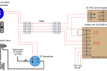
Some limit alarm trips offer the advantage of being able to provide 24Vdc power to a 2-wire (loop-powered) transmitter (Figure 19). This saves the cost of specifying and installing an additional instrument power supply.

Worldwide Safety Trend
Perhaps the most important role that “Hard” alarm trips will play in the future is their role in Safety Related applications.
In recent years, there has been a growing concern on improving the safety of process operations. Increased efforts to protect personnel, product, equipment and the environment stems from the possible threat of explosions, fires and toxic releases. Other interest is based on first hand accounts that improving safety and increasing reliability reduces costly downtime and production costs. These concerns led the IEC to issue standard IEC 61508 Functional Safety of Electrical/ Electronic/Programmable Electronic Safety Related Systems.
Limit alarm trips are increasingly asked to play a role in Safety Related Systems (SRS) as primary alarm stategies, to back up “soft” PLC and DCS alarms, and in other especially critical applications such as those that require 2-out-of-3 voting strategies (Figure 20).

FMEDA Reports
To help companies implement Safety Related Systems (also called Safety Instrumented Systems or SIS), some limit alarm trips are available with Failure Modes, Effects and Diagnostic Analysis (FMEDA) reports. An FMEDA is a detailed circuit and performance evaluation that estimates the failure rates, failure modes, and diagnostic capability of a device. It includes both mathematical analysis and specific physical tests.
The results of the analysis include verifying the instrument’s predictable and repeatable failure mode(s), and determining its associated failure rates. It is employed by the instrument user to determine the suitability for use of a specific device in a safety related application.
As IEC 61508 gains popularity throughout the world, we can expect to see limit alarm trips, as well as most other process instrumentation, being specifically designed and approved to the IEC 61508 standard.
Avoid Nuisance Trips: 2-Out-of-3 Voting
Some processes are simply too important to rely on a single alarm trip to make a decision. For these, limit alarm trips can be can be used in a voting strategy.
For example, one plant engineer was using 3 temperature sensors to monitor the burn-off flame of an emissions flare stack. However, when the wind blew, the flame leaning away from the stack gives a false output signal. The solution was to change the strategy to rely on low readings from two sensors to indicate no flame in a 2-out- of-3 voting scheme. This ladder rung approach creates a “flame out circuit” only in the event that two of the three alarms are tripped. Using an alarm time delay with this strategy will also help prevent false trips (Figure 20).
Source: Moore Industries


You covered all topics in alarms of control systems. Thanks
Very informative.
thanks
The images are not loading…and plz provide a “print to pdf” version link.
Okay, I will check and update.
Dear friend,
The images are not loading.
thanks and regards
some time we found one transmitter utilize for two functionality, for control and ESD trip, my question is, in which standard we can find guidance clearly mention that 1 transmitter can not use for 2 functionality (for ESD trip and for controller input)