Let’s study the working of positive and negative edge detection instruction in Siemens PLC programming with example ladder logic.
Edge Detection in PLC

Block Description
Positive RLO edge detection:
It detects the rising edge signal change in the address from 0 to 1 and displays it as RLO as 1 after the instruction. The RLO prior to the instruction is stored in the memory address.
Negative RLO edge detection:
It detects the falling edge signal change in the address from 1 to 0 and displays it as RLO as 1 after the instruction. The RLO prior to the instruction is stored in the memory address
Address Positive edge Detection:
POS compares the signal state of address 1 with the signal state from the previous scan, which stored in address 2. If the current RLO state is “1” and the previous state was “0” (detection of rising edge), the RLO bit will be “1” after this instruction.
Address Negative Edge Detection:
NEG compares the signal state of address 1 with a signal state from the previous scan, which is stored in address 2. If the current RLO state is “1” and the previous state was “0” the RLO bit will be “1” after this instruction.
Let’s try to understand the instruction in ladder logic with the example,
Example:
In most of the cutting/slicing processing systems, industries are using PLC controllers because of their guarantee of precise and stable cutting.
Let’s take it is having Start/Stop switch (I0.0) and two outputs (Q0.0, Q0.1) where laser light pulse coming out alternatively to cut the object with 1s delay until the process gets stopped.
Ladder Logic- Positive/Negative RLO edge detection:

Ladder Description:
Network 1:
The start switch is pressed to turn on Memory coil (M0.0) and timer T0 having 1 sec as preset. I0.1 is used to reset the timer. Normally closed switch of timer output is connected in series to disable the memory coil.
Network 2:
Positive RLO edge detection (P) is connected in series with M0.0 to turn on
Output Q0.0 when rising edge happens. Memory M0.1 address is used to hold the value of (P) at the time of operation.
Network 3:
Negative RLO edge detection (N) is connected in series with M0.0 to turn on
Output Q0.1 when falling edge happens. Memory M0.2 address is used to hold the value of (N) at the time of operation.
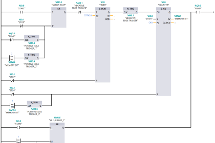
Ladder Logic- Address Positive/Negative RLO edge detection:

Ladder Description:
Network 1:
The start switch is pressed to turn on Memory coil (M0.0) and timer T0 having 1 sec as preset.I0.1 is used to reset the timer. Normally closed switch of timer output is connected in series to disable the memory coil.
Network 2:
Address Positive RLO edge detection is connected in series with I0.0 as the input condition to turn on output Q0.0 when the rising edge of M0.0 happens.
Memory M0.1 address is given to the M Bit, used to hold the value of the instruction at the time of operation.
Network 3:
Address Negative RLO edge detection is connected in series with I0.0 as the input condition to turn on output Q0.0 when falling edge of M0.0 happens.
Memory M0.2 address is given to the M Bit, used to hold the value of the instruction at the time of operation.
Author: Hema Sundaresan
If you liked this article, then please subscribe to our YouTube Channel for PLC and SCADA video tutorials.
You can also follow us on Facebook and Twitter to receive daily updates.
Read Next: