In this article, you will learn the wiring in a PLC control panel and the basic electrical design of a PLC system cabinet.
Wiring in a PLC control panel is a hectic job and requires a good understanding of PLC standards as well as electrical standards.
Basically, before PLC was being started to be used in the market, wiring was the only method to provide control of a system.
Wiring interlocks need a good understanding of the logic to be implemented as well as the electrical standards that need to be implemented to fulfill it. So, it is said the one who is a master in designing and understanding electrical wiring logic and interlock can easily write a PLC logic too.
In this post, we will see how to design a PLC system cabinet. In simpler terms, consider that you are wiring an electrical PLC panel.
Wiring in PLC
Refer to the below image. We will consider a simple panel here, with all the basic electrical components.
The PLC panel consists of the main breaker switch, bus bar, circuit breakers, relays, contactors, PLC, fuses, SMPS, terminal boards, utility sockets, and earthing points.
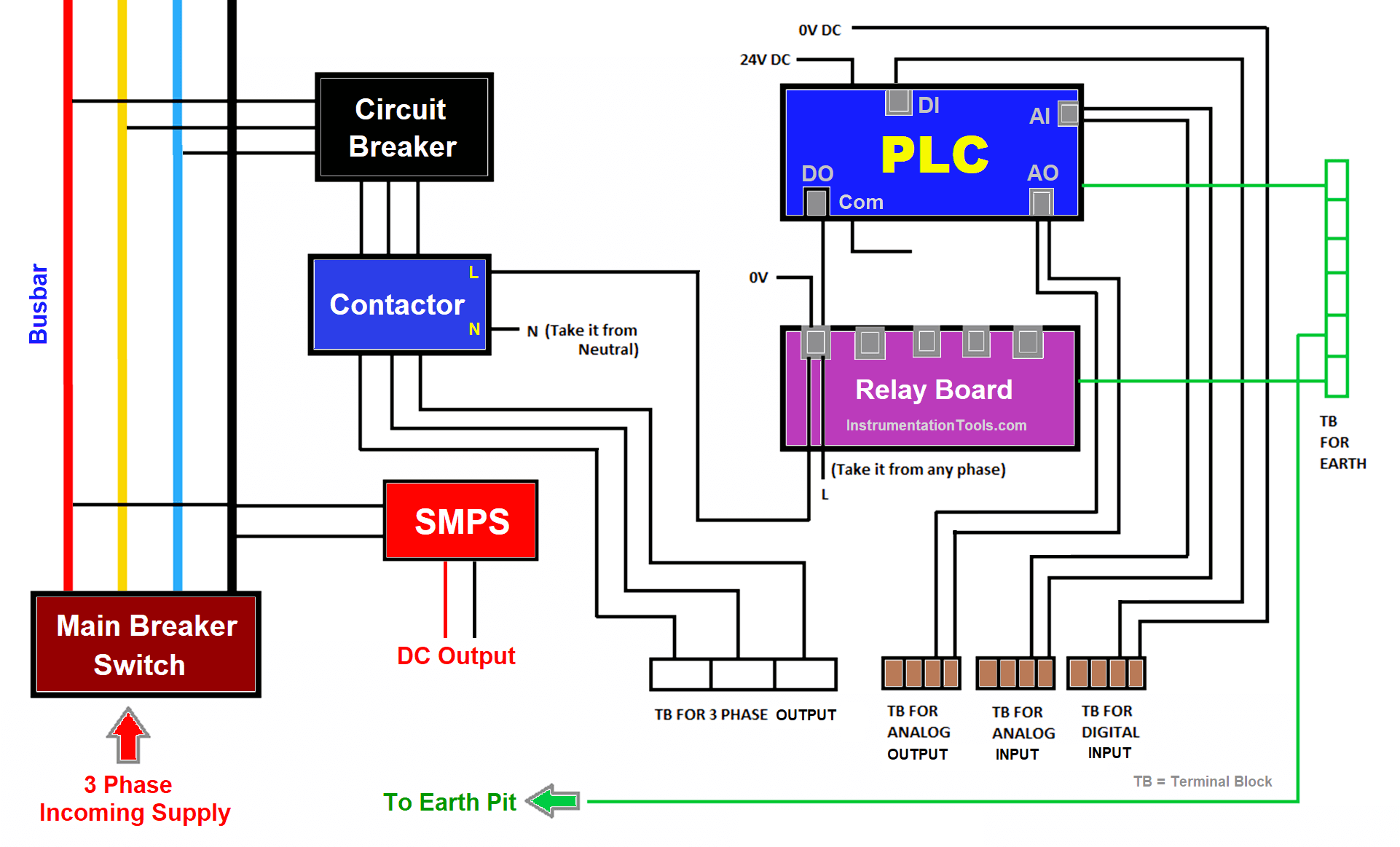
Main Breaker Switch
Let us start with the main breaker switch. This is the point where the main power supply (3 phases) is connected (R, Y, B, N). It is this point that supplies power to all the components.
Install the breaker in such a way that the wireman gets a free hand to do the wiring; because any lag in it can damage the whole system.
Busbar
In the next step, connect the output of the main breaker switch to the busbar. The bus bar provides proper electrical distribution.
So, if there are many components in the panel which requires a single-phase supply or three-phase supply, then the bus bar is the most efficient step to do it.
Distribute all the points from here to the ones which require single phase or three phase supply. This will help you in easy and efficient power management.
You cannot just loop the three-phase wires to different components, as it is a wrong practice and can damage the wiring or the whole electrical panel in totality.
Circuit Breakers
Now, suppose there are three circuit breakers in the panel. Connect the three phase wires from the bus bar to each of the circuit breaker inputs.
Individual circuit breakers will power individual contactors connected to their output. This will give proper output control to the contactors.
Because contactors have a control circuit that is controlled by the PLC; thus giving individual three-phase control too will give proper electrical control over the final output.
SMPS
Now, from the bus bar, connect one point to the SMPS. This will power it up and give DC output to the cabinet.
If the current rating of SMPS is higher, then you can use a distribution terminal board too for DC supply. This will properly segregate the DC supply to all the components requiring it. From this, power the PLC.
Now, after this, we will see how to wire the PLC IOs.
Digital Inputs
Firstly, take digital inputs. According to sink or source wiring, connect either 24V or 0V to the PLC common.
So, for example, if the common is 24V, connect 0V to all the respective PLC field inputs in the terminal board.
As one board has two pins, one will be used to provide 0V and the other will be connected to PLC digital input.
For safety, many use fuse terminal boards. This provides additional safety to the field devices.
Digital Outputs
Then, coming to digital outputs, the same sink and source theory applies to it.
So, for example, if the common is 24V, connect 0V and PLC digital outputs to all the relays (relay has two pins, so one pin will be 0V and the other pin will be PLC digital output).
According to the output you want at relay output (DC or AC), connect the wiring accordingly.
For example, if the relay output required is 230V AC, connect the line wire to the common and connect the NO wire to the contactor’s line input. Connect the neutral wire to the contactor’s neutral input and thus, the circuit is complete.
Now, whenever the relay turns on, that particular contactor will turn on and if its MCB is on, then the three-phase supply will be passed on to the final output.
Analog Inputs and Outputs
Now, analog input and analog outputs will be directly routed through terminal boards with respect to PLC.
If possible, use fused terminal boards for additional safety.
Terminal Boards
Coming back to the contactors, the output is connected to terminal boards where you can connect your final output.
Note down some general points while designing a PLC panel:
- Have a good understanding of electrical ratings and standards, before choosing a component; for example, a contactor.
- Many times, fuses are connected after the mains breaker switch to protect the panel from any damage caused by the incoming three-phase supply. Also, transformers are used in many panels to step down a voltage according to the requirements.
- Fuses are also installed after SMPS for protecting PLC or other sensitive field devices.
- If three phase devices are used with earth points, ensure to provide separate earthing (power and instrument) in the panel. Do not mix them up.
- In this example, I have not shown terminal boards for PLC digital outputs; but even they are used normally in many applications. Because there can be valves in the system which require 24V DC, and such outputs require terminal wiring in the boards.
Many types of designs are possible in a PLC cabinet. You should know the basic requirements and have a fair idea of electrical wiring and PLC wiring, which will help in designing the panel properly.
If you liked this article, then please subscribe to our YouTube Channel for Electrical, Electronics, Instrumentation, PLC, and SCADA video tutorials.
You can also follow us on Facebook and Twitter to receive daily updates.
Read Next:
- UPS Working Principle
- Electrical Wiring Diagram
- 4-20 mA Transmitter Wiring
- Why 24 Volts DC Power Supply?
- Interposing Relay Panel Wiring


I comment to learning different Electrical $ystem.
Am comment to learn and gain more knowledge partaining plc wiring