Inst ToolsInst ToolsInst Tools
  • Courses
  • Automation
    • PLC
    • Control System
    • Safety System
    • Communication
    • Fire & Gas System
  • Instrumentation
    • Design
    • Pressure
    • Temperature
    • Flow
    • Level
    • Vibration
    • Analyzer
    • Control Valve
    • Switch
    • Calibration
    • Erection & Commissioning
  • Interview
    • Instrumentation
    • Electrical
    • Electronics
    • Practical
  • Q&A
    • Instrumentation
    • Control System
    • Electrical
    • Electronics
    • Analog Electronics
    • Digital Electronics
    • Power Electronics
    • Microprocessor
  • Request
Search
  • Books
  • Software
  • Projects
  • Process
  • Tools
  • Basics
  • Formula
  • Power Plant
  • Root Cause Analysis
  • Electrical Basics
  • Animation
  • Standards
  • 4-20 mA Course
  • Siemens PLC Course
Reading: Siemens PLC Tia Portal – OB100 Start-up Organization Block
Share
Notification Show More
Font ResizerAa
Inst ToolsInst Tools
Font ResizerAa
  • Courses
  • Design
  • PLC
  • Interview
  • Control System
Search
  • Courses
  • Automation
    • PLC
    • Control System
    • Safety System
    • Communication
    • Fire & Gas System
  • Instrumentation
    • Design
    • Pressure
    • Temperature
    • Flow
    • Level
    • Vibration
    • Analyzer
    • Control Valve
    • Switch
    • Calibration
    • Erection & Commissioning
  • Interview
    • Instrumentation
    • Electrical
    • Electronics
    • Practical
  • Q&A
    • Instrumentation
    • Control System
    • Electrical
    • Electronics
    • Analog Electronics
    • Digital Electronics
    • Power Electronics
    • Microprocessor
  • Request
Follow US
All rights reserved. Reproduction in whole or in part without written permission is prohibited.
Inst Tools > Blog > PLC Tutorials > Siemens PLC Tia Portal – OB100 Start-up Organization Block

Siemens PLC Tia Portal – OB100 Start-up Organization Block

OB100 or the start-up OB is an organization block that is called and executed by the operating system once at the startup of Siemens PLC.

Last updated: April 25, 2023 3:02 pm
Mahmoud Salama
PLC Tutorials
No Comments
Share
8 Min Read
SHARE

In previous articles we started discussing different Organization blocks of TIA Portal PLCs, we talked about what OBs are, and we discussed some of the OBs like OB1- Main cyclic, OB10, and OB20 the time of day delay and time delay interrupts respectively. In this article, we will talk about the OB100 or the startup organization block in Siemens Tia Portal.

Contents
What is Start-up Organization Block (OB100)?Why need OB100?Important Notes during Start-UpSimple Program ExampleConclusion

Contents:

  • What is OB100?
  • Why need OB100?
  • Important notes during startup.
  • Simple program example.

What is Start-up Organization Block (OB100)?

OB100 or the startup OB is an organization block that is called and executed by the operating system once at the startup of the PLC, meaning once each transition from STOP to RUN mode.

The main cycle OB1 will not be called and executed until all startup functions inside OB100 are executed.

You can have more than one start-up OB in your PLC logic if that happens then the operating system will call and execute all of them one by one starting from a lower OB number to a higher number. I.e. if you have OB100 and OB123, then OB100 will be called and executed first then OB123.

After the OB100 is executed the operating system will read the input modules into the PII and starts the main cycle program OB1.

Why need OB100?

You use OB100 for a lot of tasks that you might want or need to perform before you start your cyclic logic, for these reasons are:

  • Initialize variables.
  • Reset system modules.
  • Recalibrate sensors/actuators.
  • Check for alarms and safety conditions before starting your process.

Even if you haven’t created a startup OB for your logic, the operating system still has many tasks that it needs to execute before starting your main logic, some of these tasks are:

  • Clear non-retentive memories
  • Clear the PIQ
  • Call and execute startup OBs, if any.
  • Update PII
  • Enable outputs after changing to RUN mode.

Did you notice that the last task of a startup routine is to enable the outputs? That is why the first step of executing the main cycle program OB1 is to write the PIQ into the output module.

Important Notes during Start-Up

Note the following points regarding the “STARTUP” mode:

  • The outputs on the modules are disabled.
  • The process image is initialized.
  • The process image is not updated.
    • In order to read the current state from inputs during “STARTUP”, you can access inputs via direct I/O access.
    • In order to initialize outputs during STARTUP, values can be written via the process image or via direct I/O access. The values are output at the outputs during the transition to the “RUN” mode.
  • The non-retentive bit memories, timers, and counters are initialized.
  • The non-retentive tags in data blocks are initialized.
  • During startup, no cycle time monitoring is running yet.

Simple Program Example

In this example, we will add a start-up OB100 to our PLC logic and see how many times the OB100 is executed. See picture 1 for adding a new OB100.

Tia Portal - OB100 Start-up Organization Block
Picture 1 – Add an OB100

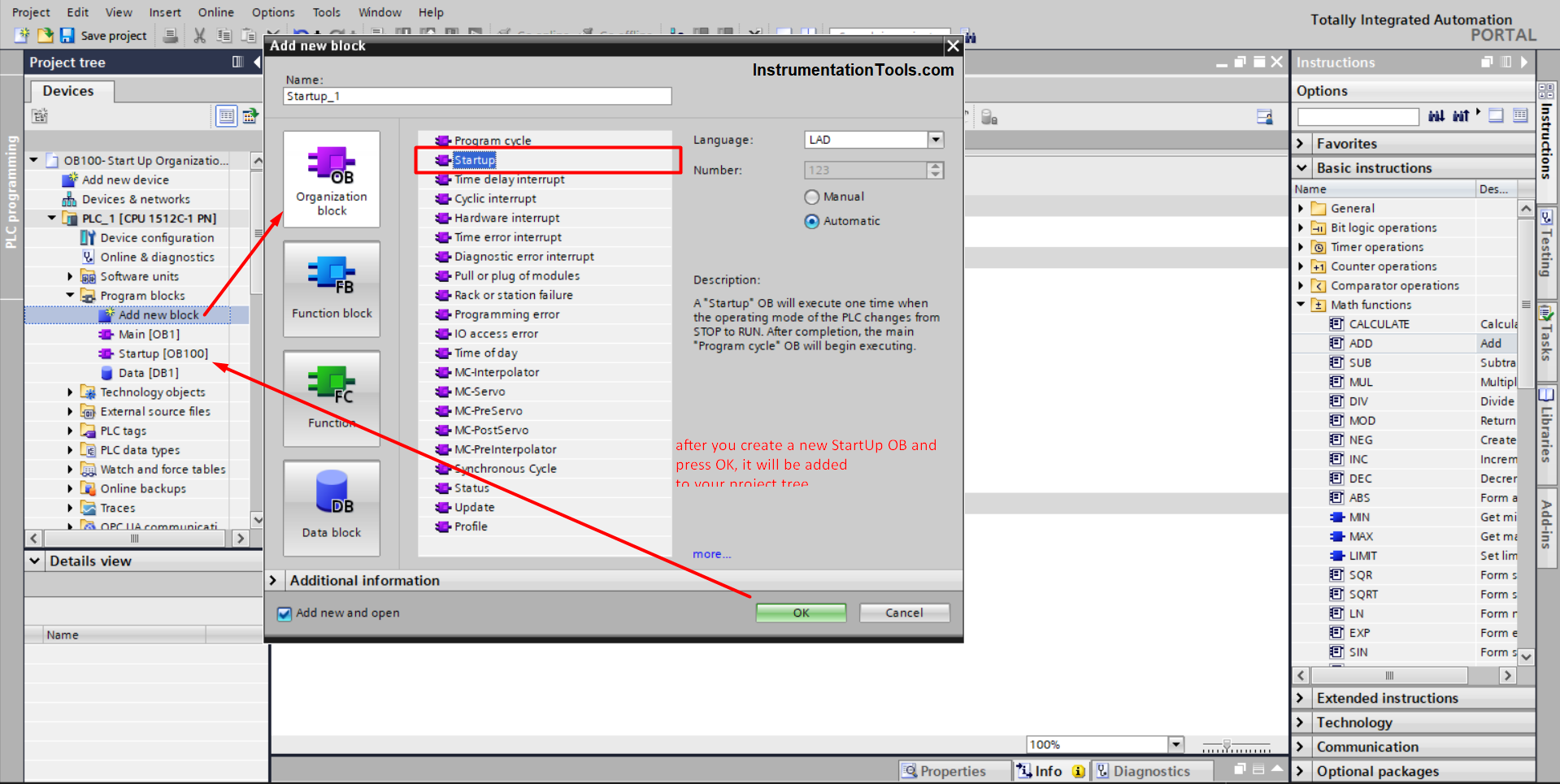
As you see from the last picture, you add startup organization blocks the same way we add a function of a function block.

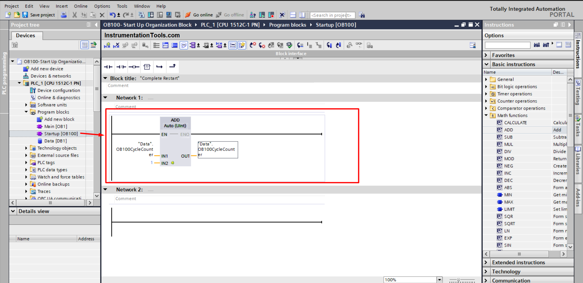
Inside the OB100 we just created we will add a simple ADD instruction, to accumulate how many times the OB100 is called and executed. See picture 2.

PLC Start-up Organization Block
Picture 2 – Accumulate execution times of OB100

Now, compile and run your program and see what will happen. See the following animation for a simulation of the PLC program.

Siemens TIA Portal – Startup OB
Animation 1

As you can see from the above animation, the OB100CycleCounter is 1 and it doesn’t change when the PLC mode transitions from STOP to RUN.

Well, it does change but you don’t see this change. Each time the PLC goes into STOP mode and then to RUN mode again. The counter will be reset to zero and then to 1 again after the OB100 is executed. You can also see the main OB1 cycle counter changing, and the PLC stops and then runs again the OB1CycleCounter will start accumulating again.

To see the change in the startup counter, we need to retain the value of the tag memory. See picture 3.

OB100 - The Startup Function
Picture 3 – Retain the OB100CycleCounter tag memory

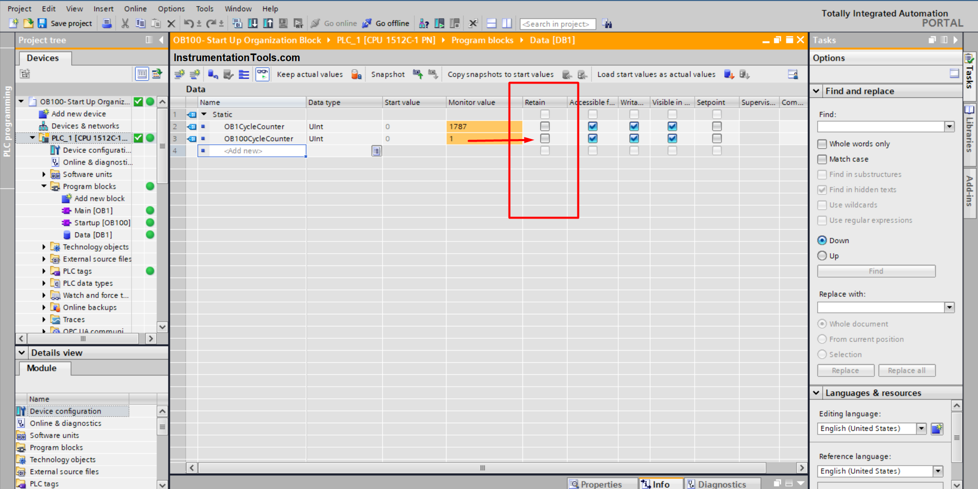
After we retain the OB100CycleCounter tag, now run the PLC simulation again and see what will happen. See simulation animation 2.

OB100 Siemens
Animation 2

You see now from the above animation, that the startup counter increases each time I stop the PLC and then start it again. As the tag memory is now retained, the value will not be reset to zero, and that is why you see the value of the OB100CycleCounter accumulates.

Now, I need to add extra functionality to my startup PLC logic, which is to know when the last startup of the PLC was. We will achieve that through a simple logic where I read the local time of the PLC at startup and move the date and time to a certain memory area. See picture 4.

S7 Organizational blocks
Picture 4 – Reading local time at start-up

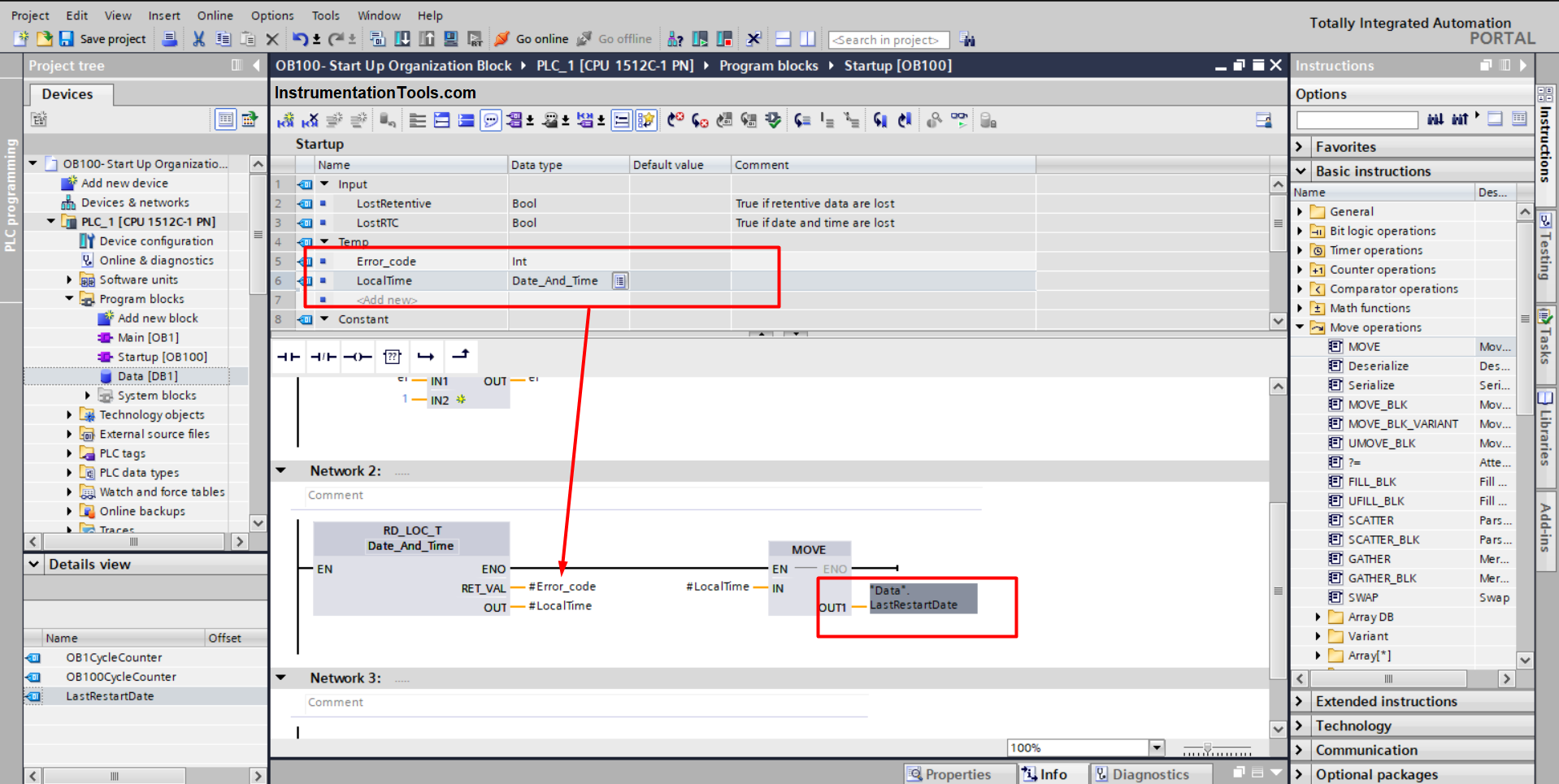
After you add your logic, compile and run the simulation again. See the PLC simulation animation 3.

Tia portal startup ob
Animation 3

You can see from the above animation, that each time the PLC starts the startup date and time will be recorded in the memory area we assigned. So now I have the information regarding how many times my PLC started and when was the last start-up time.

Downloads:

  • OB100 PLC Document
  • Start-up OB Program

Conclusion

Startup OBs are very important if you want to evaluate some functionality before you can run your cyclic process. You can use start-up OBs to initialize parameters, calibrate sensors and even check for safety conditions before allowing your process to run.

You can find more news about the PLC in Europe on IndustrieVandaag.

If you liked this article, then please subscribe to our YouTube Channel for Instrumentation, Electrical, PLC, and SCADA video tutorials.

You can also follow us on Facebook and Twitter to receive daily updates.

Read Next:

  • SCADA in an IoT System
  • HMI and VFD Control System
  • PLC Cold and Hot Standby
  • Normally-Closed Stop Buttons
  • Types of SCADA Architecture
Don't Miss Our Updates
Be the first to get exclusive content straight to your email.
We promise not to spam you. You can unsubscribe at any time.
Invalid email address
You've successfully subscribed !

Continue Reading

PLC Data Comparison Instructions
PLC Example on Manufacturing Line Assembly
Exhaust Fan Control: Example of PLC Timer Programming
Control Loops Objective Questions and Answers
Difference between PLC and HMI
4-20mA Loop Power Supply Questions and Answers
Share This Article
Facebook Whatsapp Whatsapp LinkedIn Copy Link
Share
Leave a Comment

Leave a Reply Cancel reply

Your email address will not be published. Required fields are marked *

Stay Connected

128.3kFollowersLike
69.1kFollowersFollow
210kSubscribersSubscribe
38kFollowersFollow

Categories

Explore More

Components of SCADA
Industrial Automation Pre-Engineering Design Documents – Project & Process
Move Instruction in Tia Portal
PLC Program – Controls Conveyors ON and OFF Sequence
PLC Based Industrial Conveyor Ladder Logic
Standard Colors in PLC Automation Systems
PLC Instruction List Example for Level Control of Tank
Typical HMI Screen Design for Water Treatment Plant

Keep Learning

PLC Program for Automatic Heating and Mixing of Products

Heating and Mixing of Products using PLC Example Tutorial

Run 4 Motors Sequentially from Same Push button PLC Program

Run 4 Motors Sequentially from Same Push button PLC Program

Siemens PLC Programming OBs in Siemens TIA Portal

FC Function in Siemens PLC

PLC FBD Example for Tank Liquid Heating Control by Steam Flow

PLC FBD Example for Tank Liquid Heating Control by Steam Flow

What is a GSD File and Why it is required?

What is a GSD File and Why it is required?

Siemens PLC Simulator and Plant Simulation Software

How to use Simulator in Siemens PLC?

Sequencer Output in PLC

PLC Sequencer Instruction with Example

PLC program for VFD Drive Multiple Speeds

Drive Multiple Speeds with Different Reference using PLC

Learn More

Nuclear Magnetic Resonance Spectrometer Questions and Answers

Continuous Wave NMR Spectroscopy Questions & Answers

IP transducer

Pilot Valves and Pneumatic Amplifying Relays

AC Induction Motor Construction

Basics of AC Induction Motors

Test and Electrical Measurement Objective Questions and Answers

100 Test and Electrical Measurement Objective Questions and Answers

Serial Communication Interview Questions

Serial Communication Interview Questions and Answers

Electricity and Magnetism Questions & Answers

Top 300 Electricity and Magnetism Questions & Answers

Types of Inductors

What is an Inductor? – Types of Inductors

Fieldbus Segment Design

Foundation Fieldbus Segment Design

Menu

  • About
  • Privacy Policy
  • Copyright

Quick Links

  • Learn PLC
  • Helping Hand
  • Part Time Job

YouTube Subscribe

Follow US
All rights reserved. Reproduction in whole or in part without written permission is prohibited.
Welcome Back!

Sign in to your account

Username or Email Address
Password

Lost your password?