Inst ToolsInst ToolsInst Tools
  • Courses
  • Automation
    • PLC
    • Control System
    • Safety System
    • Communication
    • Fire & Gas System
  • Instrumentation
    • Design
    • Pressure
    • Temperature
    • Flow
    • Level
    • Vibration
    • Analyzer
    • Control Valve
    • Switch
    • Calibration
    • Erection & Commissioning
  • Interview
    • Instrumentation
    • Electrical
    • Electronics
    • Practical
  • Q&A
    • Instrumentation
    • Control System
    • Electrical
    • Electronics
    • Analog Electronics
    • Digital Electronics
    • Power Electronics
    • Microprocessor
  • Request
Search
  • Books
  • Software
  • Projects
  • Process
  • Tools
  • Basics
  • Formula
  • Power Plant
  • Root Cause Analysis
  • Electrical Basics
  • Animation
  • Standards
  • 4-20 mA Course
  • Siemens PLC Course
Reading: Factory Acceptance Test (FAT) of a PLC Panel
Share
Font ResizerAa
Inst ToolsInst Tools
Font ResizerAa
  • Courses
  • Design
  • PLC
  • Interview
  • Control System
Search
  • Courses
  • Automation
    • PLC
    • Control System
    • Safety System
    • Communication
    • Fire & Gas System
  • Instrumentation
    • Design
    • Pressure
    • Temperature
    • Flow
    • Level
    • Vibration
    • Analyzer
    • Control Valve
    • Switch
    • Calibration
    • Erection & Commissioning
  • Interview
    • Instrumentation
    • Electrical
    • Electronics
    • Practical
  • Q&A
    • Instrumentation
    • Control System
    • Electrical
    • Electronics
    • Analog Electronics
    • Digital Electronics
    • Power Electronics
    • Microprocessor
  • Request
Follow US
All rights reserved. Reproduction in whole or in part without written permission is prohibited.
Inst Tools > Blog > PLC Tutorials > Factory Acceptance Test (FAT) of a PLC Panel

Factory Acceptance Test (FAT) of a PLC Panel

In this article, you will learn the general guidelines and how-to procedure of factory acceptance test (FAT) of a PLC Panel.

Last updated: April 18, 2023 12:24 pm
Viral Nagda
PLC Tutorials
No Comments
Share
6 Min Read
SHARE

In this article, you will learn the general guidelines and how-to procedure of factory acceptance test (FAT) of a PLC Panel.

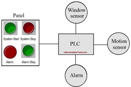
PLC system always comes in a control panel. It is not possible to run the PLC system without a control panel.

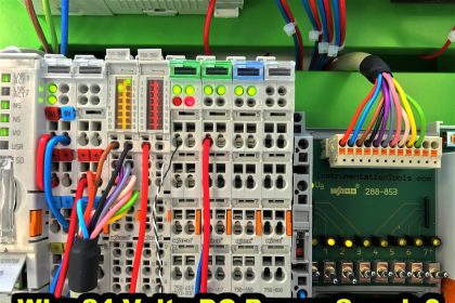
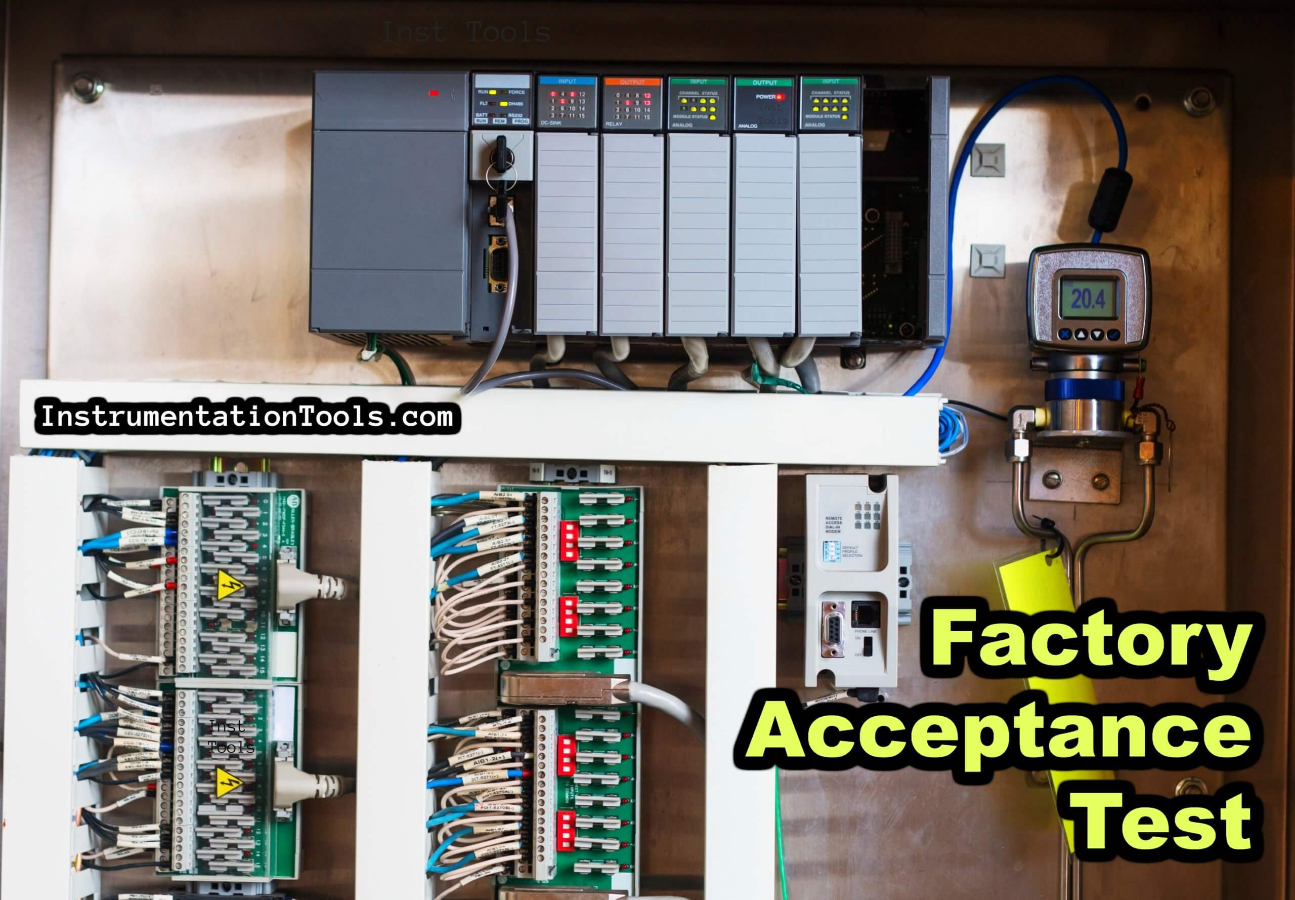
Basically, it is the electrical panel where the PLC is mounted along with other electric devices like contactors, relays, terminal boards, fuses, circuit breakers, and bus bar. All of these components comprise an electrical panel.

Factory Acceptance Test of PLC Panel

Factory Acceptance Test of PLC Panel

Suppose you have designed a PLC system and made it ready for testing. But, you need to follow some general guidelines to see whether all the components and their wiring is proper or not. This has to be done in front of the customer before dispatching it to them. This process is called FAT (Factory Acceptance Test).

So the PLC panel will be tested at the factory and only accepted by the client if it is functioning properly as per the design documents.

Let’s study the step-by-step procedure for executing a proper FAT of the system.

You first of all created documents like the IO list, electrical drawing, GA (General Architecture) of the panel, and BOM (Bill of Materials) and sent them to the customer for approval.

So, before calling them for FAT at your factory, make sure you have two hard copies of the above-mentioned documents for verification; one for you and the other for the customer to check and approve.

Now that the client is with you and ready for inspection; first of all, let them verify all the components according to BOM (Bill of material) visually. It is to be done to ensure that all the materials that you have sold to them are present in the panel or not.

Let them verify the GA of the PLC panel and visually check whether it’s proper or not.

Let them inspect the panel outdoors, fabrication, and gland hole design approved by them. So, as you must have read, this step is the visual verification of all the documents and electrical panels before powering them up.

After the visual inspection has been done, connect the main power supply to the panel and power it up.

Check the incoming voltage with a multimeter on its terminal board. Check the voltage between earth to neutral and see if it is below 0.5V. If everything is proper, then turn on all the MCBs in the panel one by one.

Turning on the MCBs and other circuit breakers means the panel is fully charged now. So, the PLC is also powered up eventually.

Now that the PLC is powered up, you have to connect your laptop or PC to it and download the final backup in it.

After downloading, keep the PLC in run mode and see if it shows any error or not. If you have HMI or SCADA also in the panel, then download its final program too.

Now, you have to check the IOs of the PLC. According to the wiring that you have done, check digital inputs first.

On giving the input at the desired terminal point in the panel or somewhere else, the corresponding PLC input address in the program must be turned on.

Then, check the digital outputs. According to the PLC output address that you have turned on, the physical PLC output must also turn on.

When it is ON, check the output voltage across it. The output is connected to a relay board mostly. If the relay turns on, then check whether its output is given to a contactor or terminal board.

The final objective is to check the output voltage coming across the terminals. Then, check the analog inputs.

On giving the input, the corresponding PLC input address in the program must be shown analog counts accordingly.

Then, check the analog outputs. According to the PLC output address that you have given counts, the physical PLC output must also give the corresponding counts.

Check the current or voltage across the terminals where the wire is connected.

Now, sum up all the points tested and make a compliance report. Give the remarks accordingly if something is faulty or pending to be checked.

If the client gives approval after testing has been completed, then your PLC panel is ready to be dispatched and FAT has been completed.

In this way, we saw the general steps in conducting the FAT of a PLC system.

If you liked this article, then please subscribe to our YouTube Channel for Instrumentation, Electrical, PLC, and SCADA video tutorials.

You can also follow us on Facebook and Twitter to receive daily updates.

Read Next:

  • Types of Noise in Electronics
  • AS-interface Communication
  • PLC System Site Acceptance Test
  • Troubleshoot the Status of a PLC
  • Control Motion using VFD drives
Don't Miss Our Updates
Be the first to get exclusive content straight to your email.
We promise not to spam you. You can unsubscribe at any time.
Invalid email address
You've successfully subscribed !

Continue Reading

How to Create New Project in Studio 5000?
The Purpose of Marshalling Cabinet or Marshalling Panel
Sheets, Tags, Elements in Functional Block Diagram of Studio 5000
PLC Digital Input and Digital Output Modules
Preventive Maintenance of Variable Frequency Drive (VFD)
How to use PLC with SQL Database? – Basics & Tutorials
Share This Article
Facebook Whatsapp Whatsapp LinkedIn Copy Link
Share
Leave a Comment

Leave a Reply Cancel reply

Your email address will not be published. Required fields are marked *

Stay Connected

128.3kFollowersLike
69.1kFollowersFollow
210kSubscribersSubscribe
38kFollowersFollow

Categories

Explore More

Electrical Switches Principle & Types
Automated Test Bench – Complex PLC Programming Examples
PLC Techniques for I/O Mapping
Various Types of Delta PLC used in Industrial Automation
What is SCADA System?
FOR DO Statement in SCL Language
Industrial Automation Engineers Interview Questions
Automation System for Hazardous Environments

Keep Learning

Functional block diagram for analog alarms

PLC Logic for Analog Alarms using Functional Block Diagram

OpenPLC - PLC Training for Students - Free Tutorials & Courses

OpenPLC – PLC Training for Students – Free Tutorials & Courses

Top Non-PLC Certification Courses for Automation Professionals

Top Non-PLC Certification Courses for Automation Professionals

Sequencer Output in PLC

PLC Sequencer Instruction with Example

Dry Contact in PLC

What is a Dry Contact? – Basics of PLC Wiring

PLC Program for Blinking Lamp on 5 Seconds Interval

PLC Program for Blinking Lamp on 5 Seconds Interval

Advanced Skills Required for a PLC Programmer to Get a Job

Advanced Skills Required for a PLC Programmer to Get a Job

PLC program for Latching and unlatched circuit

PLC Program for Latching and unlatching Circuit

Learn More

Interview Questions on Instrumentation

Interview Questions for Instrumentation

pressure-gauge-animation

Bourdon Tube Pressure Gauge Working Principle Animation

Control Systems Questions & Answers

Control Systems Objective Questions & Answers – Set 8

Electrical Systems vs. Pneumatic Systems

Electrical Systems vs. Pneumatic Systems

Self-actuated Temperature Regulator

Self-actuated Temperature Regulator – Principle, Types, Advantages

How Engineers Effectively do Problem-solve and Troubleshoot

How Engineers Effectively do Problem-solve and Troubleshoot?

PLC Program for Boolean Expression

PLC Program for Boolean Expression

Phase Watcher Multiphase Flow Meter (MPFM) Procedure

Menu

  • About
  • Privacy Policy
  • Copyright

Quick Links

  • Learn PLC
  • Helping Hand
  • Part Time Job

YouTube Subscribe

Follow US
All rights reserved. Reproduction in whole or in part without written permission is prohibited.
Welcome Back!

Sign in to your account

Username or Email Address
Password

Lost your password?