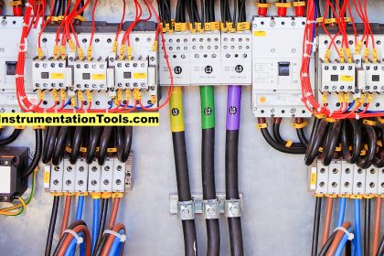
A circuit breaker is the one device in switchgear that operates during any abnormal fault condition in an electrical system i.e. overcurrent, earth fault, and short circuit, thus isolating a faulty electrical circuit from the healthy electrical circuit.
Switchgear is switching equipment used in an electrical system for various applications. The general specifications of the circuit breaker are operating voltage, nominal current, making capacity, breaking capacity, and the duty cycle.
Circuit breakers can also be operated manually or from a remote location as per requirement in an electrical system.
Circuit breakers are made for various voltage and current ratings depending on is applications. Circuit breakers are classified according to arc quenching medium for extinguishing arc during the opening of a breaker.
Classification of Circuit Breakers
| Features | ACB | MOCB | ABCB | VCB | SF6 |
| Voltage Range LV: <1000 V, MV: 1KV to 33KV HV: 33 to 220KV, EHV: ≥440 KV | LV | MV | MV HV EHV | MV | MV HV EHV |
| Construction IMC- internal metal clad GIS – Gas insulated OPC – outdoor porcelain clad IK – indoor Kiosk | IMC | IMC OPC | IK OPC | IMC IK GIS | IMC OPC GIS |
| Maintenance | less | maximum | less | Nil | less |
| Contact life Max – 100 short circuits | less | less | more | maximum | more |
| Explosion possibilities | less | maximum | less | Nil | less |
| Fire Hazard | less | maximum | Nil | Nil | Nil |
| Capacitor switching NS- not suitable, S – suitable | NS | NS | S | S | S |
| Repeated operation NS- Not suitable, S – Suitable | S | NS | S | S | S |
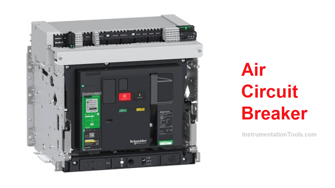
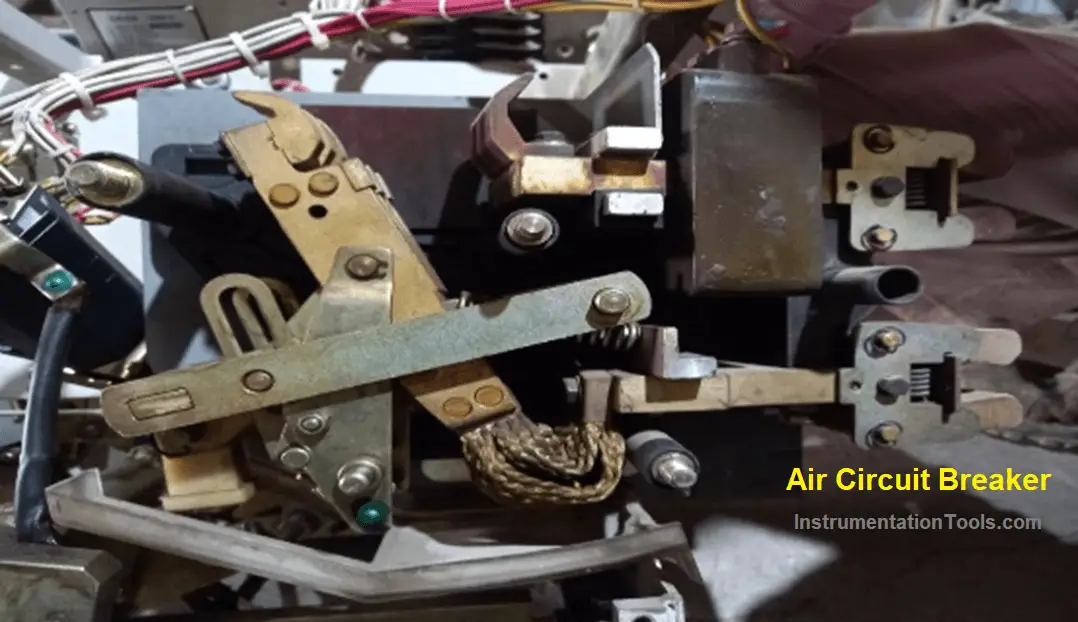
What is Air Circuit Breaker?
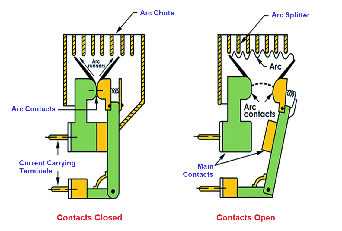
An air circuit breaker consists of fixed and moving contacts that are enclosed in an arc chute chamber having air as an arc quenching medium.
These circuit breakers are usually used for low voltage applications (up to 1000 V). Its current rating ranges from 500 amps to 10000 amps.
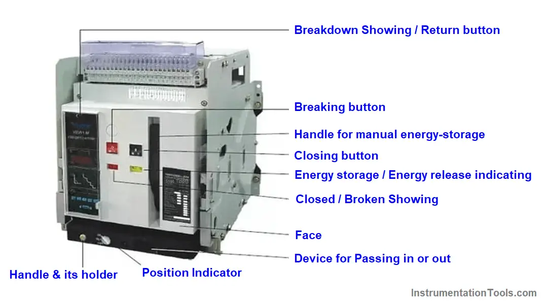
Air Circuit Breaker (ACB) Construction
A low voltage Air Circuit Breaker (ACB) has compact construction. All poles of an ACB having fixed and moving contacts are housed in an arc chute assembly. These breakers can be operated both electrically and mechanically through a triggering mechanism.
These breakers are provided with rack-in and rack-out features with sliding and guide rail assembly. Push buttons are mounted on ACB for its manual operations.
ACBs are also provided with inbuilt CTs, relay, and trip unit provisions.
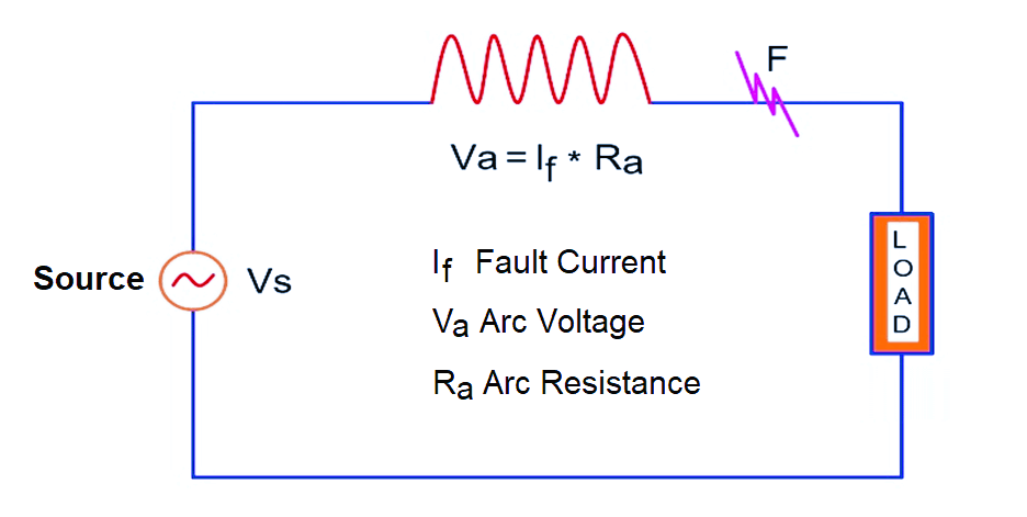
Working Principle
The air circuit breaker employs a high resistance interruption method for arc extinction.
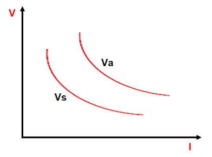
Resistance of the arc is rapidly increased to a high value during the opening of a circuit breaker in fault or normal operating condition such that source voltage becomes incapable to maintain arc voltage.
Arc Resistance Ra can be increased by many methods such as
- Cooling the arc
- Lengthening the arc
- Reducing the cross-section of the arc
- Splitting the arc
Types of Air Break Circuit Breaker
- Plain Break Type ACB or Cross-Blast ACB
- Magnetic Blowout Type ACB
- Magnetic Blowout Type ACB
- Magnetic Blowout Type ACB
Applications of Air Circuit Breakers
- Air Circuit Breakers are mainly used for Low voltage and Low/high current applications.
- Air Circuit Breakers are used mostly in indoor low to medium-voltage electrical installations such as Power control cubicles & Motor control cubicles.
- Air Circuit Breakers are preferred for applications where there is a high risk of fire hazards as ACBs have a very short arcing time.
- Air Circuit Breakers are used for motor & capacitor starting and protection applications as they are most suitable for frequent and high-speed operations.
- Air blast type circuit breakers are widely used in railways electrifications
If you liked this article, then please subscribe to our YouTube Channel for Electrical, Electronics, Instrumentation, PLC, and SCADA video tutorials.
You can also follow us on Facebook and Twitter to receive daily updates.
Read Next:
DOL Starter Circuit Diagrams
Earth Leakage Circuit Breaker
Star Delta Starter Circuit Diagrams
Control Two Motors after Time Delay
Thermal Protection Relay for Motors