Relays
Relays are constructive elements that make contacts and control some energy expenditure. With the relays, it is possible to control a power much higher with very low power consumption. The relays are used to process signals, and can also be used as switches.
A normal relay is an electrical device that works like an electrically operated switch, when the current reaches the relay coil, the open contacts get close, and the closed contacts get open. When no current reaches the relay coil, the contacts return to their normal position, the initial state of rest.
What are Time Relays?
A basic function within the industry is time control, all this process can be carried out by timing relays.
No matter what the application is when a solution to a circuit that requires time control is needed, these tools are usually the most optimal option. Because, timed relays provide simple control, and high reliability and are also quite economical.
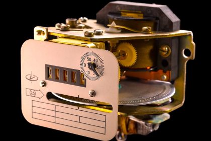
Timed Relays
Now, when the opening or closing of the contacts of a relay depends on a certain time after activating or deactivating the relay coil, they are called “Timed Relays” or Electrical Timers or Timer Relays.
With a timer relay, we can establish the connection time of any output element of an electrical circuit, such as a lamp, a contractor, etc.
A timed relay is nothing but a control relay with time delay built-in.
In this article, we study the most used timing relays. We will learn how they work, their timing diagrams, connections, uses, etc.
Principle of Time delay Relay
Time delay relay provides a change of state of the contacts that are controlled by the energizing or de-energizing of the timer.
Once the timer is energized or de-energized, the timer starts counting from zero to the present time. This is called accumulated time.
Once accumulated time and pre-set time are equal the contact of the timer change the state.
Types of Timing Relays
Depending on when the time for the relay contacts to change position begins, we have 2 main types.
Timer Relay with Connection Delay
This is also known as “On Delay” or “ To work with delay”. Whose contacts change position after a time since the timer coil began to activate (energize).
On-Delay Timer
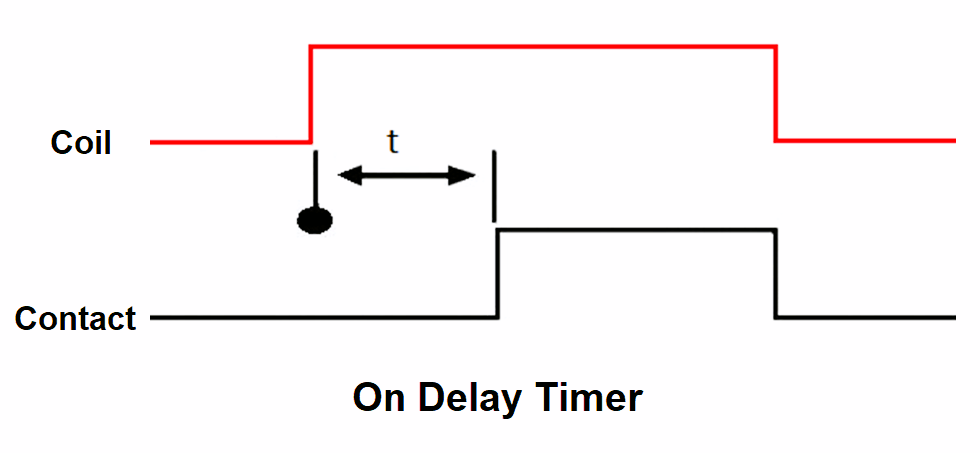
Once the current reaches the timer coil, after a time “t”, the contacts change position, that is, the ones that were open close and the closed contacts open (working state).
They will stay that way as long as the coil is powered.
They will return to their initial state (at rest) when no current reaches the timing relay coil. If the power supply to the coil is cut, at that moment, the contacts return to their resting state automatically.
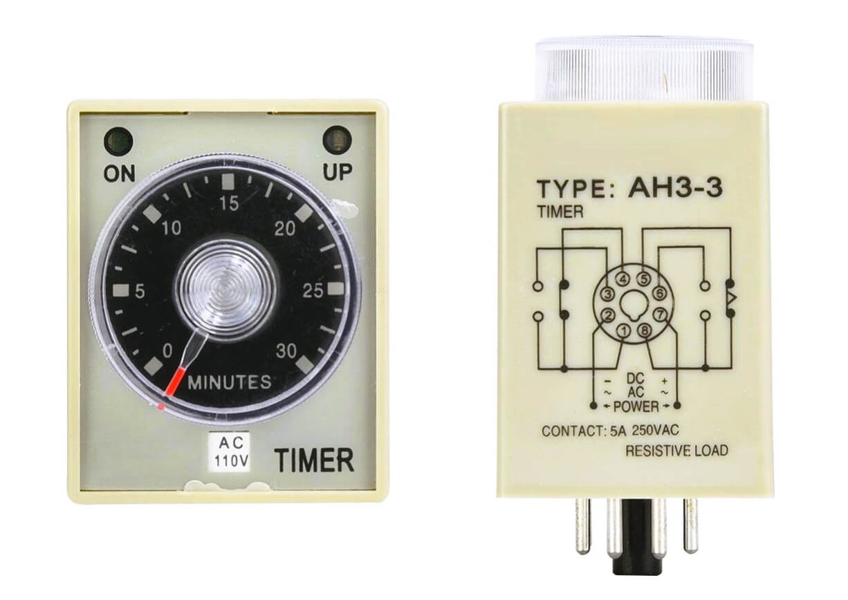
The time is regulated by using a rotary knob built into the timer itself. The pre-set time can be from as few as milliseconds to hours and even days. But it is usually set in seconds and minutes in industrial control systems.
Timer Relay with Disconnection Delay
Also known as sleep delay or “Off Delay”. In these times, the contacts change position as soon as the current reaches the coil. As soon as the coil is deactivated, the deactivation time “t” starts to lapse, so that they start to return to their initial state (rest).
The “t” represents the time between the moment the coil is disconnected and the moment the contacts change their positions.
As long as the coil is energized, the contacts will be in the working position.
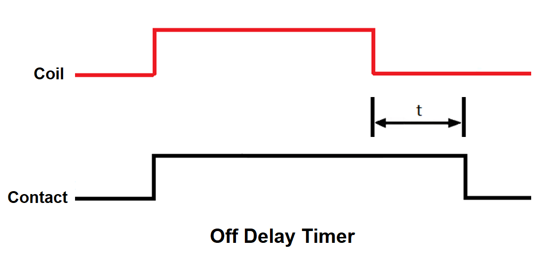
Off-Delay Timer
In this diagram, the contacts return to their resting positions “t” seconds after the coil is deactivated.
The diagram below does not specify the time, but the activation is called a trigger, and the contacts or outputs, output.
This type of timer can be used for automatic stairs. When we press and release a button, the lamps will remain ON for the time t. For example, 2 minutes after releasing the button.
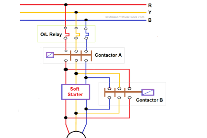
Another use may be for star-delta starting control of the motor. When pressing the button and releasing it, the motor starts in “star”, after a certain time, for example, 5 seconds, it enters the “delta” start.
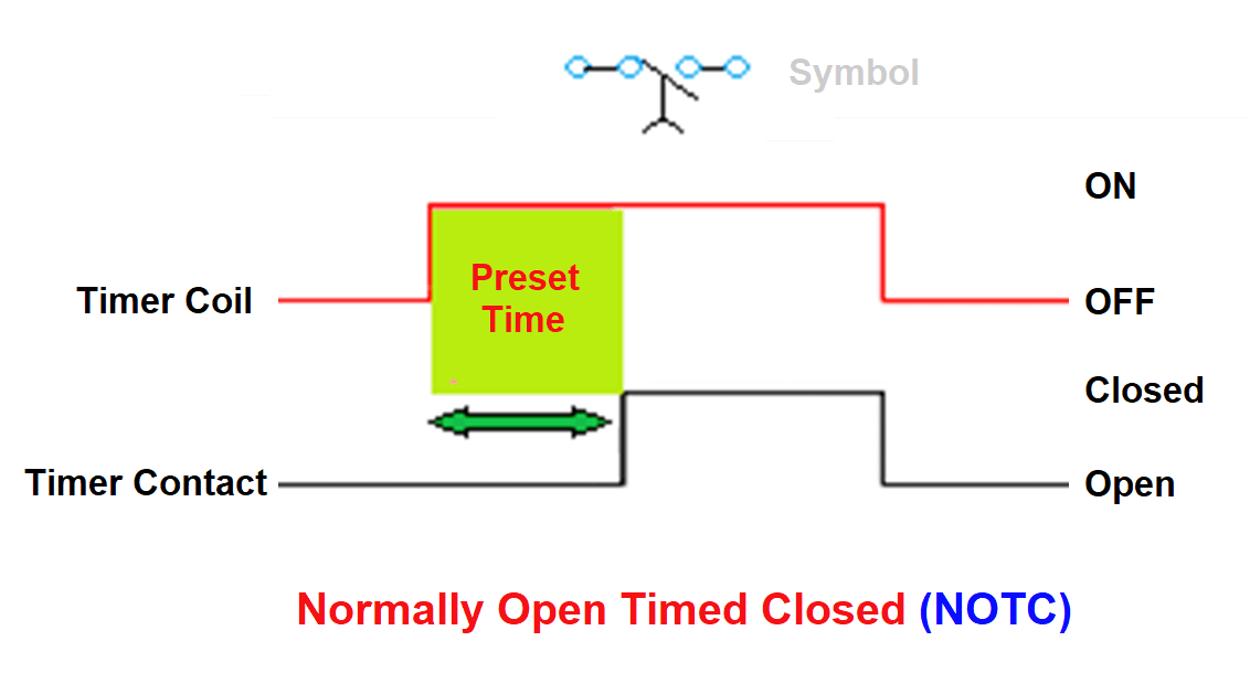
Normally Open Timed Closed (NOTC)
Normally open, (instant open), time delay close (NOTC) upon energizing. It means that when the relay is energized, the contact closes only after a certain time delay.
The contact opens immediately (instant open) upon de-energization of the relay coil.
Normally Closed Timed Open (NCTO)
Normally closed, (instant close), time delay open (NCTO) upon energization. In this type, when the relay is energized, the contact opens only after a time delay.
The contact closes immediately upon the de-energization of the relay coil.
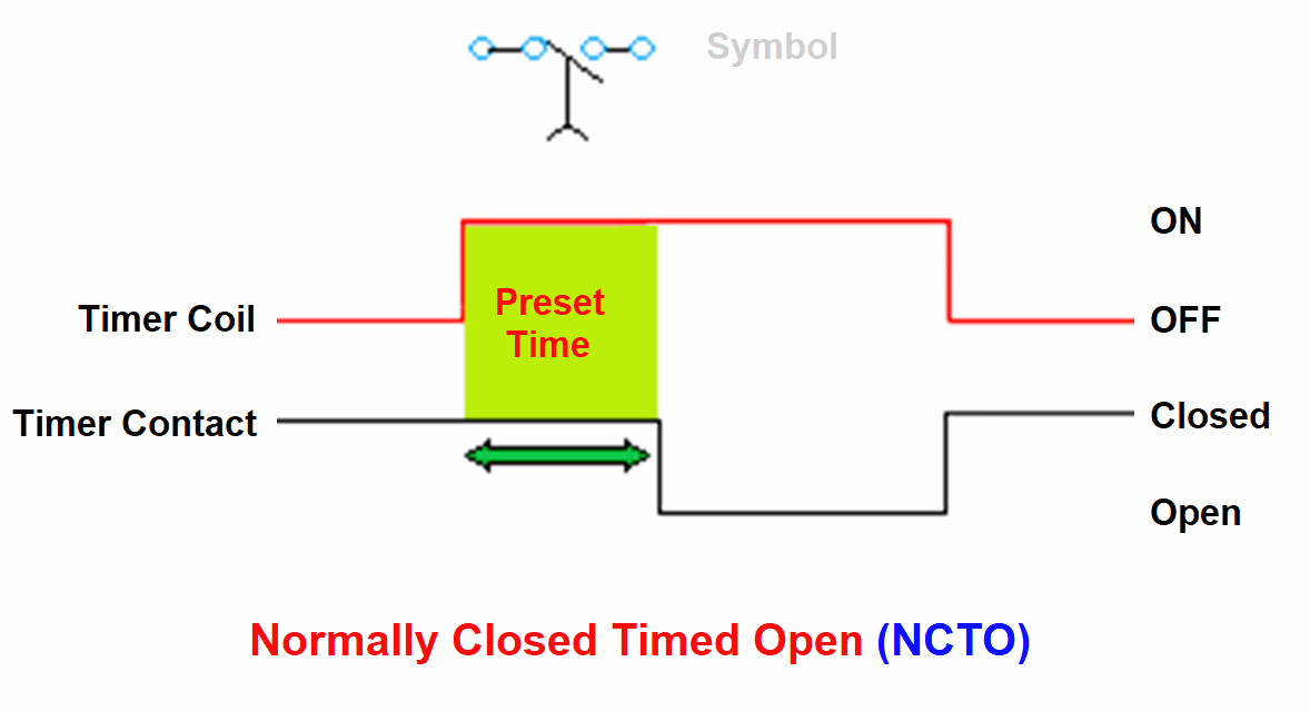
This is the same as the previous relay except that normally closed contacts are used.
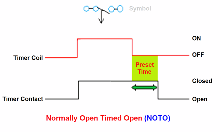
Normally Open Timed Open (NOTO)
Normally open, (instant close on energization), time delay open (NOTO) after de-energization.
As soon as the relay is energized, the contact will close and remain closed for some time after power is removed from the coil.
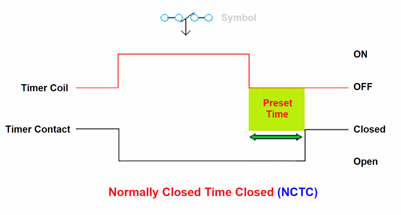
Normally Closed Time Closed (NCTC)
Normally closed, (instant open on energization), time delay close after de-energization (NCTC), this is similar to the previous relay except that the normally closed contacts are used.
Advantages of Time Delay Relays
- Time delay relays are useful in implementing control logic with electronic control systems.
- Time delay relay helps in scheduling the start or stop of machinery.
- Time delay relay helps to set delay time from a few seconds to even hours.
- Energy saving is possible.
Applications of Time Delay Relays
- Automatic Control
- Remote control
- Communication
- Electronic equipment
If you liked this article, then please subscribe to our YouTube Channel for Instrumentation, Electrical, PLC, and SCADA video tutorials.
You can also follow us on Facebook and Twitter to receive daily updates.
Read Next:
DOL Starter Circuit Diagrams
Earth Leakage Circuit Breaker
Star Delta Starter Circuit Diagrams
Control Two Motors after Time Delay
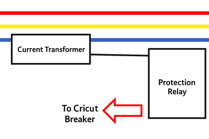
Thermal Protection Relay for Motors