Relay Logic or “Classic Control” as we call it nowadays, is the birth and beginning of Industrial Automation Technology.
“PLCs” are the most commonly used devices these days, and also it is invented to overcome and replace the use of complicated classic control circuits.
However, an Automation Engineer mindset cannot be perfect without a deep understanding of classic control circuits.
So, today we are going to experience a classic control application that is used in most factories, and also it is a common interview question.
Functional Design Specification (FDS) of our application
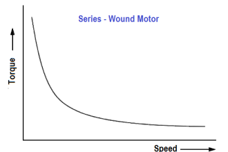
A major part of any factory is a Three-Phase Induction Motor, it is commonly used for most industries so you might find a sector in a factory that contains many motors.
The simplest way to handle the operation of these motors is by Start/Stop control circuit, it is a simple circuit and it uses two push buttons (NO one for start & NC for stop).
But you have to consider that a panel with many pushbuttons may be confusing for the operators.
So, what we need is to make a circuit that can handle a motor with just NO push-button:
- On the occurrence of the first press… the motor will run.
- For the second press, the motor will stop… and so on.
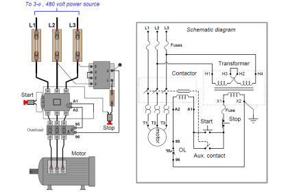
Motor Classic Control Circuit Explanation
Here you can see in Fig. (1) the classic control circuit that can execute our task, and we will understand this circuit in simple steps.
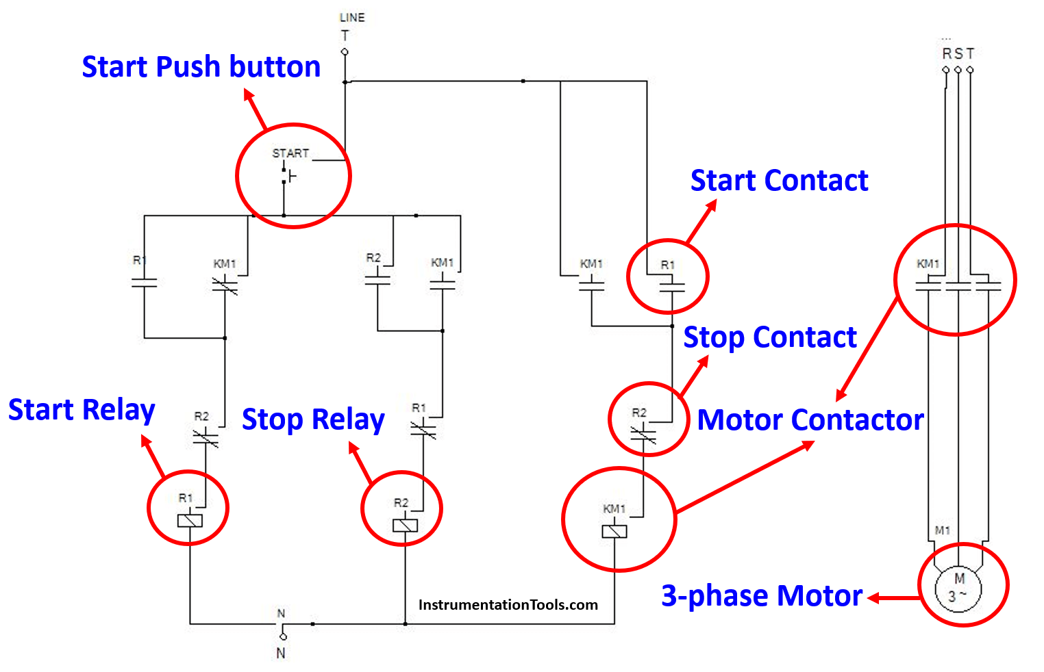
Main Idea
As you can see in Fig. (1) we are using a single NO push-button, two relays, and a motor contactor.
The main idea of this circuit stands behind the two relays, the NO push button is made to handle the two relays (one relay for starting the motor contactor and the other for stopping).
Also, the contact that is taken from (KM1) as you can see in Fig (1) if the motor is off the start relay will be ready to be energized, and if the motor is running its contact will change so, the stop relay will be ready to be energized.
Circuit De-energized
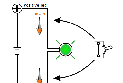
As you can see in Fig. (2) when the circuit is de-energized the logic flow goes towards the start relay (R1).
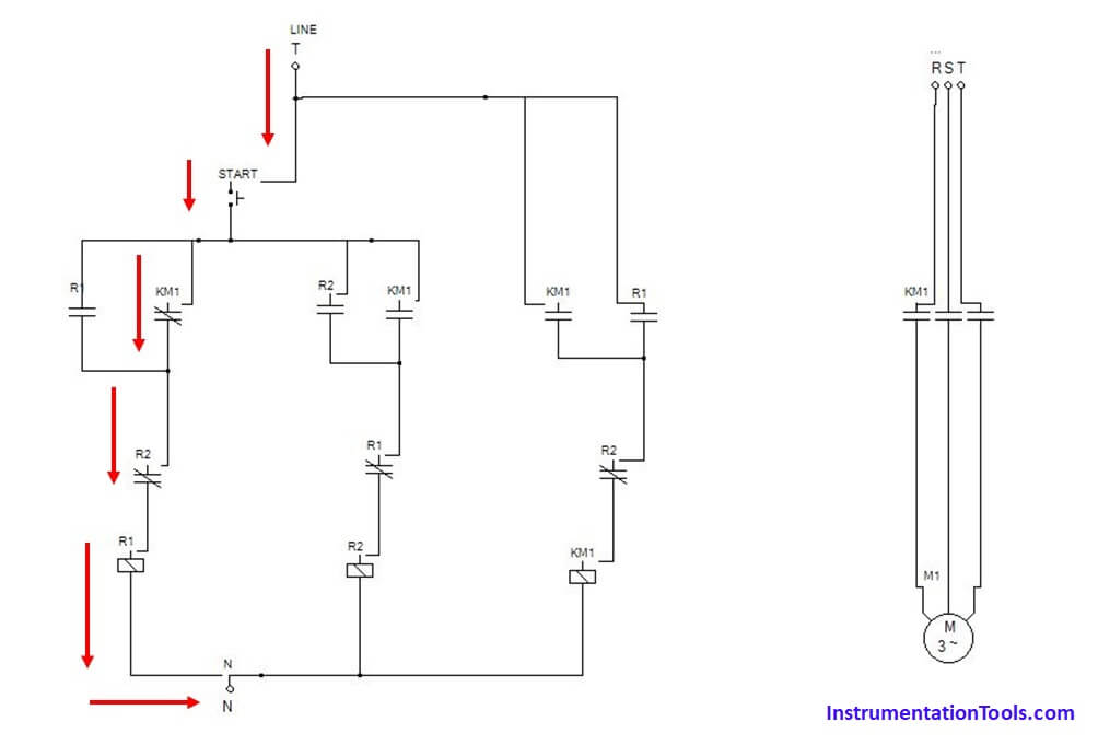
So, in case of pressing on the NO push button, the start relay will be energized to operate the motor.
Circuit Energized
As you can see in Fig. (3) when we press the NO push button and the circuit is energized the logic flow goes towards the stop relay (R2).
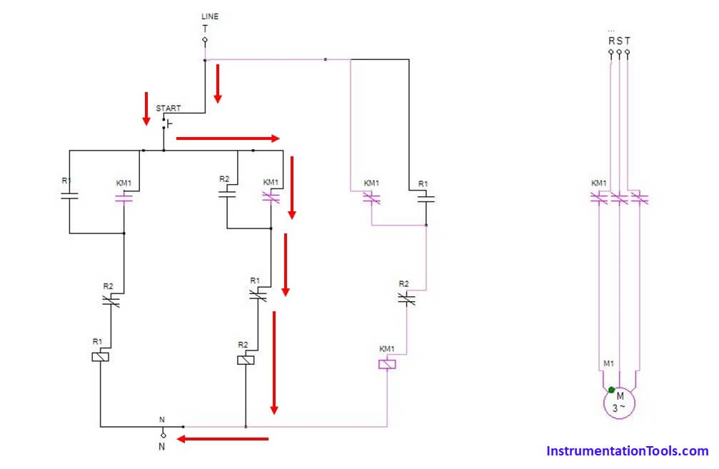
In this case, the motor is running but as you can see if we press the NO push button the stop relay (R2) will be energized and the motor will stop.
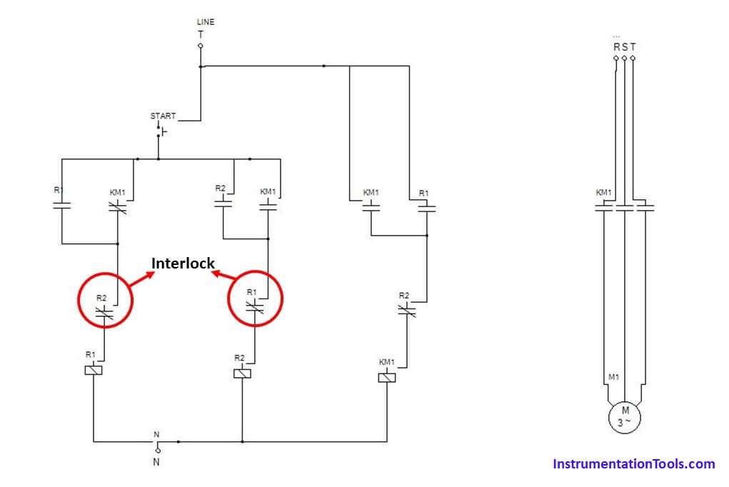
Interlocking between two Relays
In Fig. (4) we can see that there is an interlock between the two relays, this interlock prevents the two relays from overlapping.
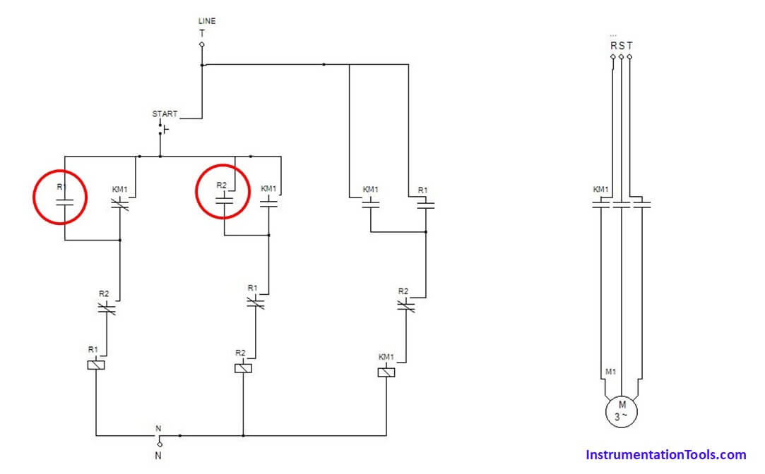
Latching on both Relays
These latches on the start/stop relays that are presented in Fig. (5) also prevent the two relays from overlapping while we are pressing the NO push button.
If you liked this article, then please subscribe to our YouTube Channel for Instrumentation, Electrical, PLC, and SCADA video tutorials.
You can also follow us on Facebook and Twitter to receive daily updates.
Read Next:
- Scan Cycle in SIEMENS PLC
- Cloud-Based SCADA Projects
- PLC-based Gas Detection System
- Create New Project in Studio 5000
- Rockwell Allen Bradley PLC Projects