Create a ladder diagram for controlling a batch mixing process. Implement a PLC program for the mixing tank or Mixing Process using PLC Ladder Logic.
PLC Program for Mixing Tank

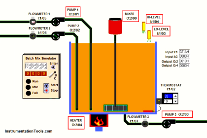
Fig : Mixing tank
A tank is used to mix two liquids.
The required control circuit operates as follows:
A. When the START button is pressed, solenoids A and B energize. This permits the two liquids to begin filling the tank.
B. When the tank is filled, the float switch trips. This de-energizes solenoids A and B and starts the motor used to mix the liquids together.
C. The motor is permitted to run for 1 minute. After 1 minute has elapsed, the motor turns off and solenoid C energizes to drain the tank.
D. When the tank is empty, the float switch de- energizes solenoid C.
E. A STOP button can be used to stop the process at any point.
F. If the motor becomes overloaded, the action of the entire circuit will stop.
G. Once the circuit has been energized, it will continue to operate until it is manually stopped.
PLC Logic Solution
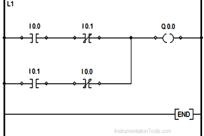
A relay schematic that will perform the logic of this circuit is shown in Below Figure. The logic of this circuit is as follows:

Fig : Relay Schematic
A. When the START button is pushed, relay coil CR is energized. This causes all CR contacts to close. Contact CR-1 is a holding contact used to maintain the circuit to coil CR when the START button is released.
B. When contact CR-2 closes, a circuit is completed to solenoid coils A and B. This permits the two liquids that are to be mixed together to begin filling the tank.
C. As the tank fills, the float rises until the float switch is tripped. This causes the normally closed float switch contact to open and the normally open con- tact to close.
D. When the normally closed float switch opens, solenoid coils A and B de-energize and stop the flow of the two liquids into the tank.
E. When the normally open contact closes, a circuit is completed to the coil of a motor starter and the coil of an on-delay timer. The motor is used to mix the two liquids together.
F. At the end of the one minute time period, all of the TR contacts change position. The normally closed TR-2 contact connected in series with the motor starter coil opens and stops the operation of the motor.
Normally open TR-3 contact closes and energizes solenoid coil C which permits liquid to begin draining from the tank. The normally closed TR-1 contact is used to assure that valves A and B cannot be re-energized until solenoid C de-energizes.
G. As liquid drains from the tank, the float drops. When the float drops far enough, the float switch trips and its contacts return to their normal positions. When the normally open float switch contact reopens and de-energizes coil TR, all TR contacts return to their normal positions.
H. When the normally open TR-3 contact reopens, solenoid C de-energizes and closes the drain valve. Contact TR-2 recloses, but the motor cannot restart because of the normally open float switch contact.
When contact TR-1 re-closes, a circuit is completed to solenoids A and B. This permits the tank to begin refilling, and the process starts over again.
I. If the STOP button or overload contact opens, coil CR de-energizes and all CR contacts open. This de- energizes the entire circuit.
Note : The PLC Program also will be very much similar to the above relay schematic.
Assignment For You
Analyse the below animation and share the circuit operation through comments.

If you liked this article, then please subscribe to our YouTube Channel for PLC and SCADA video tutorials.
You can also follow us on Facebook and Twitter to receive daily updates.
Read Next:
- Failsafe Wiring Practices
- Relay Loop Back Circuit
- PLC Program for Motor Starter
- Switch Types and Terminology
- Introduction to PLC Diagrams


Very knowledgeable
thanks a lot!
thanks a lot of stuff for practice .I have TW trainer , can do a number of programs
1)What is the usage of TR 1?
2)what is the set value of TR 1?
Can someone help me please?
Mixing Station:
When button 1 is pressed and held, valve 1 should open allowing material to flow, when button 1 is released, valve 1 should close.
When button 2 is pressed and held, valve 2 should open allowing material to flow, when button2 is released, valve 2 should close.
when button 3 is pressed and held, valve 3 should open to drain the tank, when button 3 is released valve 3 should close.
when button 4 is pressed and held, valve 1 and 2 should both open allowing both materials to flow into the tank, button 4 should also turn on the motor to mix the materials, when button 4 is released, valves 1 and 2 should close and the motor should start.
can someone please help me with the motor please?
Thank you so much!