This article about “PLC programming to control the level in the tank using three point conductive level switches for motor start & stop logic”.
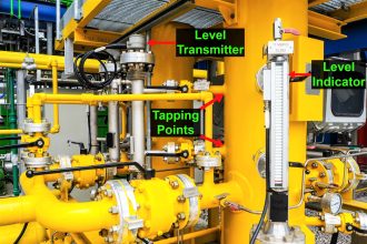
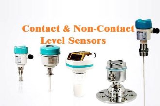
The level measurement plays a vital role in every industry from small scale sectors to complex oil and gas industries. Different types of sensors available for level measurement like ultrasonic, radar, differential pressure based sensors, etc. These sensors are used for continous level measurment which scales from 0% to 100% of level.
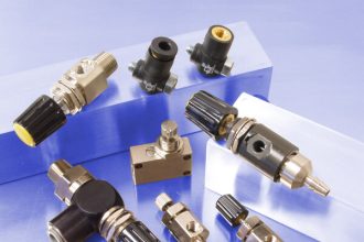
In some applications, we may need to establish a level control loop with less investment and there will be only need to maintain or control specific levels in the vessels or tanks. In these cases, we can use simple level switches for controlling the level at fixed points like Low, Medium, and High levels.
Here in our example, we are using a three probes type conductive level switches for point level detection. A Programmable logic controller (PLC) is used to control the motor based on the level switches status. These level witches are inexpensiive and needs less maintenance. Three lamps are used to indicate the level switches status.
PLC Programming using Level Switches

PLC Problem
- When the level is low then the motor (pump) will remain ON till high level reaches, lamp L1 also turns ON and gives an indication of the low level, It will remain ON till it reaches a half level (medium level).
- When the level reaches half (medium level) then the L2 lamp will turn ON & give an indication of half level. L1 goes OFF and the pump will remain ON.
- When the level reaches to high level then the pump goes OFF and lamp L3 will turn ON.
Inputs:
- Low Level Switch – S1_LL (I0.0),
- Medium or Half Level Switch – S2_HL (I0.2),
- High Level Switch – S3_HL (I0.3)
Outputs:
- PUMP (Q4.0),
- Low Level Lamp Indication (L1) – LL_LAMP1 (Q4.1),
- Medium or Half Level Lamp Indication (L2) – HL_LAMP2 (Q4.2),
- High Level Lamp Indication (L3) – HL_LAMP3 (Q4.3)
Ladder Logic
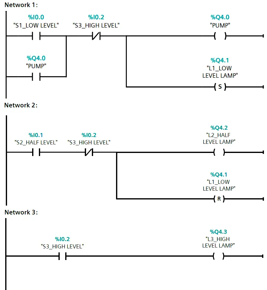
PLC Logic Description
Network 1:
when level is low (S1), lamp 1 (LL_LAMP 1) and pump will be ON. Lamp indication of low level is set to ON till level reaches medium level then it will reset (OFF). Normally closed (NC) contact of S3 is used to prevent lamp to turning on together.
Network 2:
When the level reaches a medium level (S2) then lamp 2 will turn ON and pump will remain ON. Lamp of low level indication will reset (OFF) when level reaches medium level. Same as 1st network NC contact is used for Interlocking purpose.
Network 3:
When the level reaches high level (S3) then pump will turn OFF and high indication lamp will turn ON. As the lamp 3 is ON, the motor will be de-energized & lamp 2 indication will be OFF because lamp 3 NC contact becomes open in the network 1 & 2.
Author: Suhel Patel
If you liked this article, then please subscribe to our YouTube Channel for PLC and SCADA video tutorials.
You can also follow us on Facebook and Twitter to receive daily updates.
Read Next:
- How to use JUMP Instruction
- Program to Count Running Hours
- Water Level Control Logic
- Tank Level Detection Switches
- Industrial Automation Systems


A note regarding the safety aspect and fault tolerance.
Any device used for a safety or a high level or overflow, should itself be a Normally Closed device. When the device is operational the top switch should always be passing a signal to the PLC. If high level is reached, then your input goes off and you then stop the pump. If you lose power to the switch, the same thing happens.
If the device was wired up like a typical NC switch, then if hte power to the switch fails, you will never know that you have reached the high level.