Inst ToolsInst ToolsInst Tools
  • Courses
  • Automation
    • PLC
    • Control System
    • Safety System
    • Communication
    • Fire & Gas System
  • Instrumentation
    • Design
    • Pressure
    • Temperature
    • Flow
    • Level
    • Vibration
    • Analyzer
    • Control Valve
    • Switch
    • Calibration
    • Erection & Commissioning
  • Interview
    • Instrumentation
    • Electrical
    • Electronics
    • Practical
  • Q&A
    • Instrumentation
    • Control System
    • Electrical
    • Electronics
    • Analog Electronics
    • Digital Electronics
    • Power Electronics
    • Microprocessor
  • Request
Search
  • Books
  • Software
  • Projects
  • Process
  • Tools
  • Basics
  • Formula
  • Power Plant
  • Root Cause Analysis
  • Electrical Basics
  • Animation
  • Standards
  • 4-20 mA Course
  • Siemens PLC Course
Reading: What is Electrical Busbar? Types, Advantages, Disadvantages
Share
Font ResizerAa
Inst ToolsInst Tools
Font ResizerAa
  • Courses
  • Design
  • PLC
  • Interview
  • Control System
Search
  • Courses
  • Automation
    • PLC
    • Control System
    • Safety System
    • Communication
    • Fire & Gas System
  • Instrumentation
    • Design
    • Pressure
    • Temperature
    • Flow
    • Level
    • Vibration
    • Analyzer
    • Control Valve
    • Switch
    • Calibration
    • Erection & Commissioning
  • Interview
    • Instrumentation
    • Electrical
    • Electronics
    • Practical
  • Q&A
    • Instrumentation
    • Control System
    • Electrical
    • Electronics
    • Analog Electronics
    • Digital Electronics
    • Power Electronics
    • Microprocessor
  • Request
Follow US
All rights reserved. Reproduction in whole or in part without written permission is prohibited.
Inst Tools > Blog > Electrical Basics > What is Electrical Busbar? Types, Advantages, Disadvantages

What is Electrical Busbar? Types, Advantages, Disadvantages

A busbar is a metallic bar in a switchgear panel used to carry electrical power from incoming feeders and distributes to outgoing feeders.

Last updated: October 17, 2023 3:18 pm
R Jagan Mohan Rao
Electrical Basics
2 Comments
Share
5 Min Read
SHARE

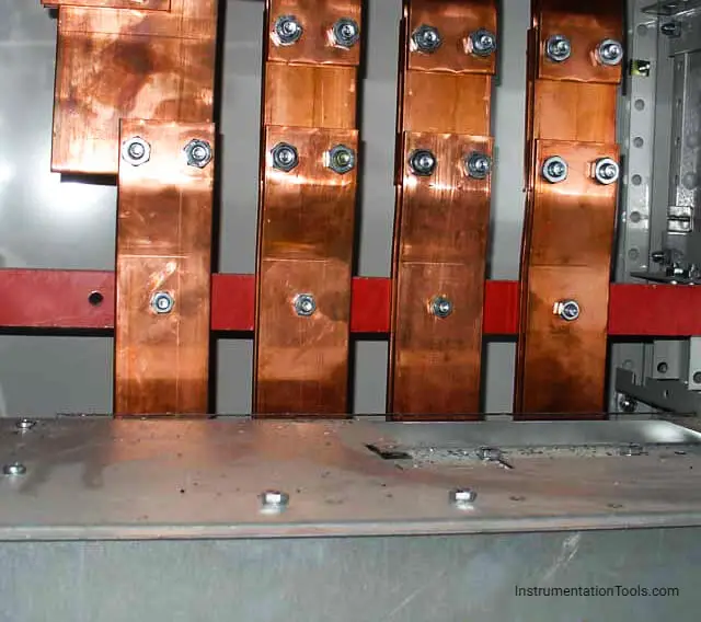
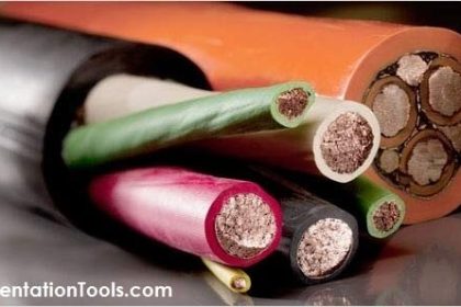
A busbar is a metallic bar in a switchgear panel used to carry electric power from incoming feeders and distributes to the outgoing feeders. In simple terms, busbar is a electrical junction where incoming and outgoing currents exchange.

Contents
Electrical BusbarPurpose of Bus-barTypes of bus barsSingle bus-bar SystemDouble Bus-bar SystemRing Bus-bar System

Electrical Busbar consists the number of lines electrically, which are operating at the same voltage and frequencies. Generally, copper or aluminum conducting material is used in the construction of bus bars.

They are used either in the form of pipe or thin-walled tubes.

Electrical Busbar

Types of busbars

Purpose of Bus-bar

Bus bars are arranged in a different configurations, any particular arrangement of bus-bar is to achieve adequate operating flexibility, sufficient reliability and minimum cost.

The circuit breakers are arranged to get the maximum availability to plant operations.

Types of bus bars

Important bus-bar arrangements are discussed in this article. Based on the construction of the bus bar, they are divided as follows.

  • Single bus-bar system.
  • Double bus-bar system.
  • Ring bus-bar system.

Single bus-bar System

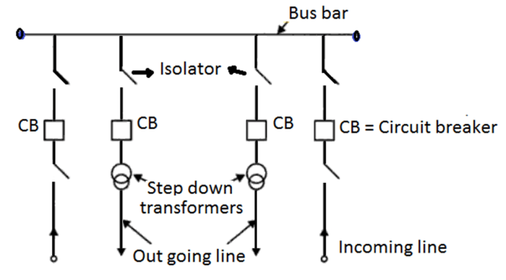
As the name itself indicates, that a single bus-bar is used in this system. To the same single bus-bar few incoming and outgoing line are connected.

As an example, two 11 KV incoming lines are connected through circuit breaker and isolator. Three phase, 440 V and single phase 230 V outgoing supply lines are connected by isolator, circuit breaker, and step down transformer as shown in the above figure.

Single bus-bar sectionalized arrangement can be made by adding circuit breakers wherever required.

Advantages of Single bus-bar System

  • The advantage of this system is that fault on one part of the bus-bar does not completely shut down the total system.
  • It has low maintenance cost.

Disadvantages of Single bus-bar System

  • In case of fault, the complete system will be switched off.
  • For any expansion, complete shutdown is to be carried out.

Double Bus-bar System

Double Bus-bar system

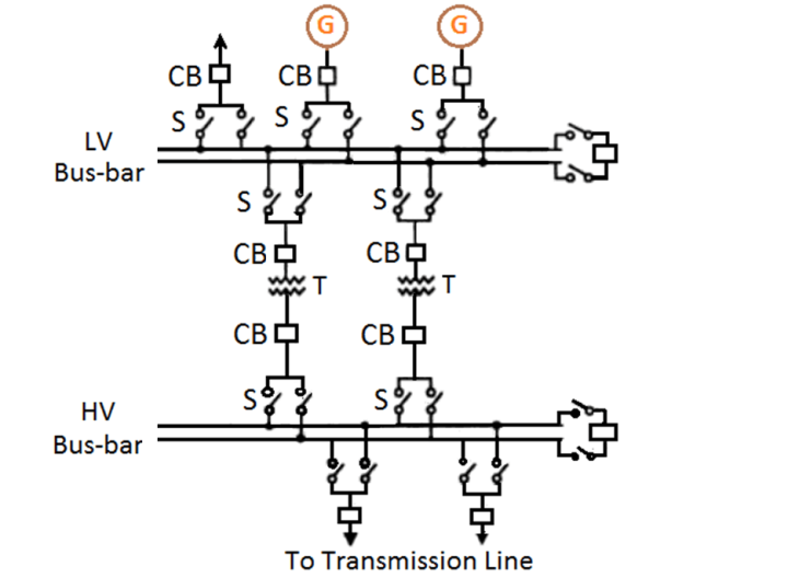
In case of double bus-bar system, low voltage and high voltage bus-bars are duplicated. Among the two, any one of the bus-bar sections can be used as desired.

There is an arrangement of a bus-bar coupling switch for transferring operation from one bus-bar to another.

Double bus-bar sectionalized arrangement can be made as per the requirement by the addition of circuit breakers.

Advantages of Double Bus-bar System

  • In the double bus-bar type of arrangement, it is possible to have one bus-bar “energized” and become convenient to carry out repairs on the other whenever required.
  • By keeping the main bus-bar un-touched, testing of feeder circuit breakers can be done by putting them on spare bus bar.
  • Whenever a fault occurs on the bus-bar, the undisrupted supply to the circuit can be maintained by transferring it to other bus-bar.

Disadvantages of Double Bus-bar System

  • Maintenance cost is high.

Ring Bus-bar System

Ring Bus-bar system

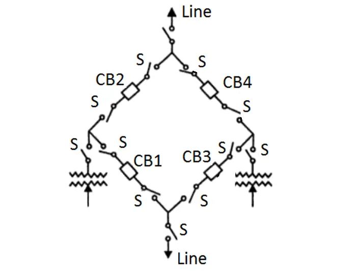
In this type of arrangement, two circuit breakers serve on one line. For example CB1 and CB2 on one line, where are CB3, CB4 on another line.

This ring bus-bar system has the advantage that there are always two parallel paths to the circuit and failure of one path does not interrupt the service completely.

Advantages of Ring Bus-bar System

  • This ring bus-bar system has redundant path to the circuit and failure of one section does not interrupt the service completely.
  • Maintenance of any circuit breaker is possible, without interruption of power.

Disadvantages of Ring Bus-bar System

  • It may be difficult in adding new circuit line.

References

  • Power System Engineering by R.K Rajput.
  • Transmission and distribution of power (WBSCTE)

If you liked this article, then please subscribe to our YouTube Channel for Instrumentation, Electrical, PLC, and SCADA video tutorials.

You can also follow us on Facebook and Twitter to receive daily updates.

Read Next:

  • Current Limiting Reactors in Power System
  • Substation Interview Questions Answers
  • Earthing Practices Used for PLC Panel
  • Comparison of Soft Starter and VFD
  • Download Electrical Enclosure Book
Don't Miss Our Updates
Be the first to get exclusive content straight to your email.
We promise not to spam you. You can unsubscribe at any time.
Invalid email address
You've successfully subscribed !

Continue Reading

Why is HV Testing important in Electrical Panels?
What is a Current Transformer?
VFD Pros and Cons – Variable Frequency Drives
NO vs NC Contact
Difference Between Core and Shell Transformers
Assembling an Electrical Conduit Seal
Share This Article
Facebook Whatsapp Whatsapp LinkedIn Copy Link
Share
2 Comments
  • Umesh Chathuranga says:
    May 9, 2022 at 3:48 pm

    it is good for beginner who interest to electrical system.

    Reply
  • Kally says:
    November 24, 2024 at 1:22 am

    Great stuff, am loving it..

    Reply

Leave a Reply Cancel reply

Your email address will not be published. Required fields are marked *

Stay Connected

128.3kFollowersLike
69.1kFollowersFollow
210kSubscribersSubscribe
38kFollowersFollow

Categories

Explore More

Electrical Contactor, Switch, Circuit Breaker
Electrical Power Grid Automation
Electric Motors Efficiency Classes
Automatic Motor Forward and Reverse Control using Timer
Motor Protection Circuits
Dahlander Motors – Principle, Advantages, Disadvantages
Shutter Door Control using Motor and Limit Switches
Advantages of Three Phase System Compared to Single Phase System

Keep Learning

Electric Stress Control in Cables, Joints and Terminations

Electric Stress Control in Cables, Joints, and Terminations

What are Switchgear Interlocks?

What are Switchgear Interlocks?

Control Methods in Servo Motor Drives

Various Control Methods in Servo Motor Drives

Why is Motor Control Required in Control Systems

Why is Motor Control Required in Control Systems?

Difference Between MCB and MCCB

Difference Between MCB and MCCB

Switched Mode Power Supply (SMPS)

How does SMPS Works? – Switched Mode Power Supply

What is a Bus Coupler in Electrical Panel

What is a Bus Coupler in Electrical Panel?

What is Trunking

Difference Between Trunking and Conduit

Learn More

Instrument Calibration Record

How to Create Calibration Records?

HR Interview Questions & Answers

HR Interview Questions and Answers

Non-Contacting-Radar-Level-Transmitter-Animation

Non Contacting Radar Level Transmitter Animation

Process variable to 4-20mA Conversion

Formula to Calculate 4-20 mA from Process Variable

Troubleshooting Fieldbus Devices

Troubleshooting Fieldbus Devices

Weinview HMI

How to Connect Mitsubishi FX3U PLC with Weinview MT6071iE HMI?

The Control Valve Stroke Test Procedure

Control Valve Stroke Test Procedure

Transformers Questions & Answers Part-2

Transformers Questions & Answers Part-2

Menu

  • About
  • Privacy Policy
  • Copyright

Quick Links

  • Learn PLC
  • Helping Hand
  • Part Time Job

YouTube Subscribe

Follow US
All rights reserved. Reproduction in whole or in part without written permission is prohibited.
Welcome Back!

Sign in to your account

Username or Email Address
Password

Lost your password?