Inst ToolsInst ToolsInst Tools
  • Courses
  • Automation
    • PLC
    • Control System
    • Safety System
    • Communication
    • Fire & Gas System
  • Instrumentation
    • Design
    • Pressure
    • Temperature
    • Flow
    • Level
    • Vibration
    • Analyzer
    • Control Valve
    • Switch
    • Calibration
    • Erection & Commissioning
  • Interview
    • Instrumentation
    • Electrical
    • Electronics
    • Practical
  • Q&A
    • Instrumentation
    • Control System
    • Electrical
    • Electronics
    • Analog Electronics
    • Digital Electronics
    • Power Electronics
    • Microprocessor
  • Request
Search
  • Books
  • Software
  • Projects
  • Process
  • Tools
  • Basics
  • Formula
  • Power Plant
  • Root Cause Analysis
  • Electrical Basics
  • Animation
  • Standards
  • 4-20 mA Course
  • Siemens PLC Course
Reading: How to Configure PID in Siemens PLC?
Share
Font ResizerAa
Inst ToolsInst Tools
Font ResizerAa
  • Courses
  • Design
  • PLC
  • Interview
  • Control System
Search
  • Courses
  • Automation
    • PLC
    • Control System
    • Safety System
    • Communication
    • Fire & Gas System
  • Instrumentation
    • Design
    • Pressure
    • Temperature
    • Flow
    • Level
    • Vibration
    • Analyzer
    • Control Valve
    • Switch
    • Calibration
    • Erection & Commissioning
  • Interview
    • Instrumentation
    • Electrical
    • Electronics
    • Practical
  • Q&A
    • Instrumentation
    • Control System
    • Electrical
    • Electronics
    • Analog Electronics
    • Digital Electronics
    • Power Electronics
    • Microprocessor
  • Request
Follow US
All rights reserved. Reproduction in whole or in part without written permission is prohibited.
Inst Tools > Blog > PLC Tutorials > How to Configure PID in Siemens PLC?

How to Configure PID in Siemens PLC?

In this article, we will learn how to configure PID controller in Siemens PLC using Tia portal programming software.

Last updated: September 28, 2022 4:10 pm
Viral Nagda
PLC Tutorials
No Comments
Share
4 Min Read
SHARE

In this article, we will learn how to configure PID controllers in Siemens PLC using Tia portal programming software.

Contents
Configure PID in Siemens PLCSiemens Tia PLC Course

PID is a very important function block in controlling various analog parameters like temperature, flow, pressure, etc. through modulating outputs.

This modulation helps in keeping the parameters hovering around a control set-point and accurately controlling the process. PID function is available in various PLCs and also some standalone microcontrollers.

Also, there are some specific PID controllers available in the market which are designed to just handle the PID process.

Various PLCs have different types of PID configuration according to the software design. In this post, we will have a look at the PID configuration in Siemens PLC.

Configure PID in Siemens PLC

Let us see step by step how to configure a simple PID in Siemens PLC.

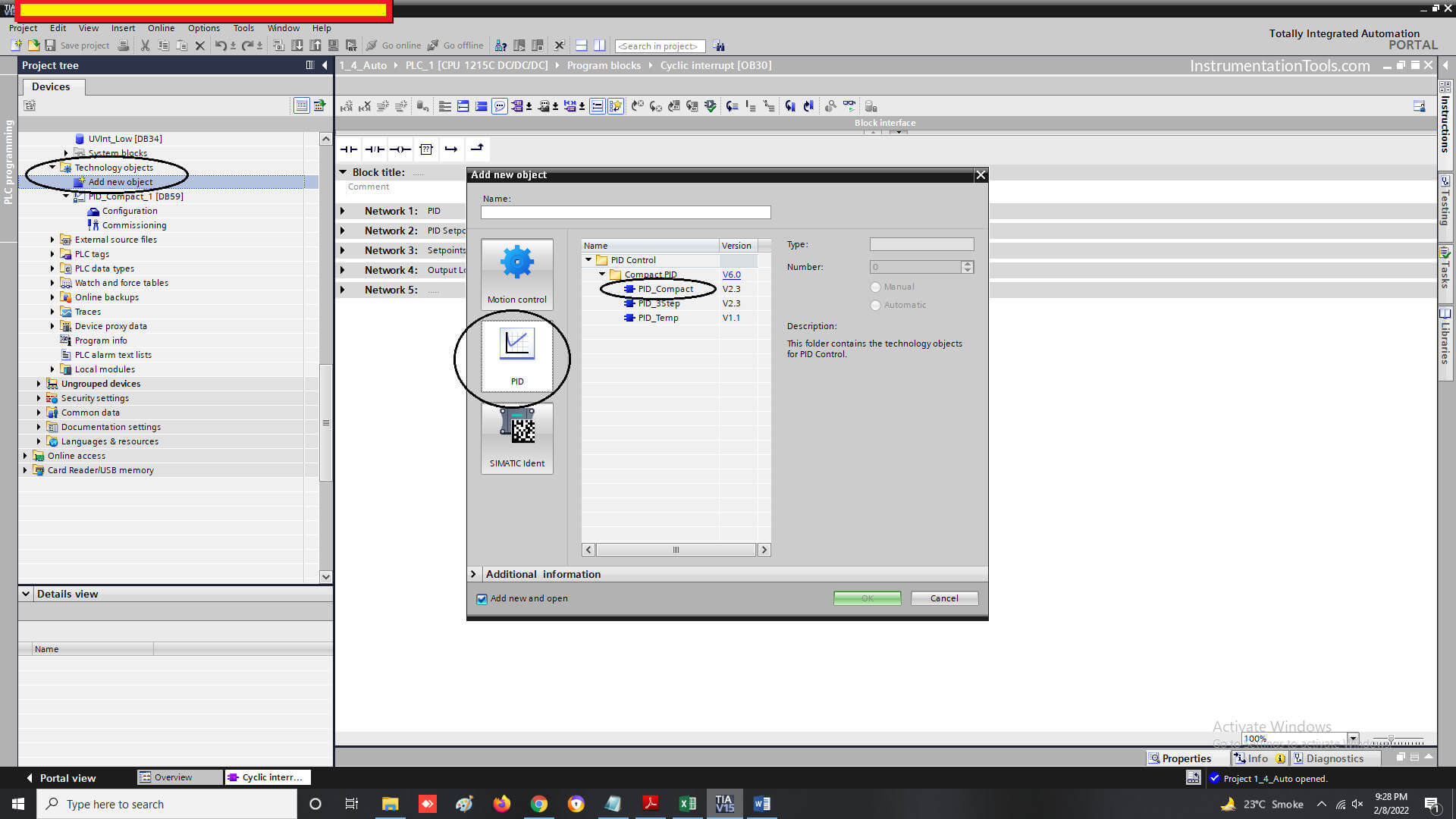
On opening the software, add a new object in Technology objects as shown in the figure. On clicking it, a popup window will open to add a new technology object.

In the PID window, select PID_Compact; which will add a PID controller in the software.

There are two other PID types available as shown in the figure; but here, we will see a simpler type that is widely used.

How to Configure PID in Siemens PLC

When the block is added, click the Configuration tab under the PID block added. A whole new window of configuration parameters will open.

In the next step, we will first see the series of images where basic configuration parameters need to be edited for PID working.

PID in Siemens TIA Portal Software
PID Control in SIEMENS PLC
PID with a Siemens S7-1200 PLC

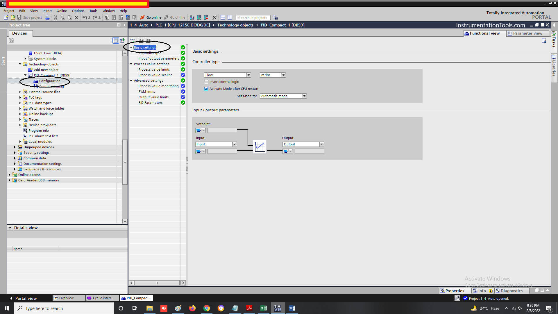
In the basic settings screen, as shown in the first image, you have to select the analog sensor type to be controlled, its unit, mode selection, its input type and output type.

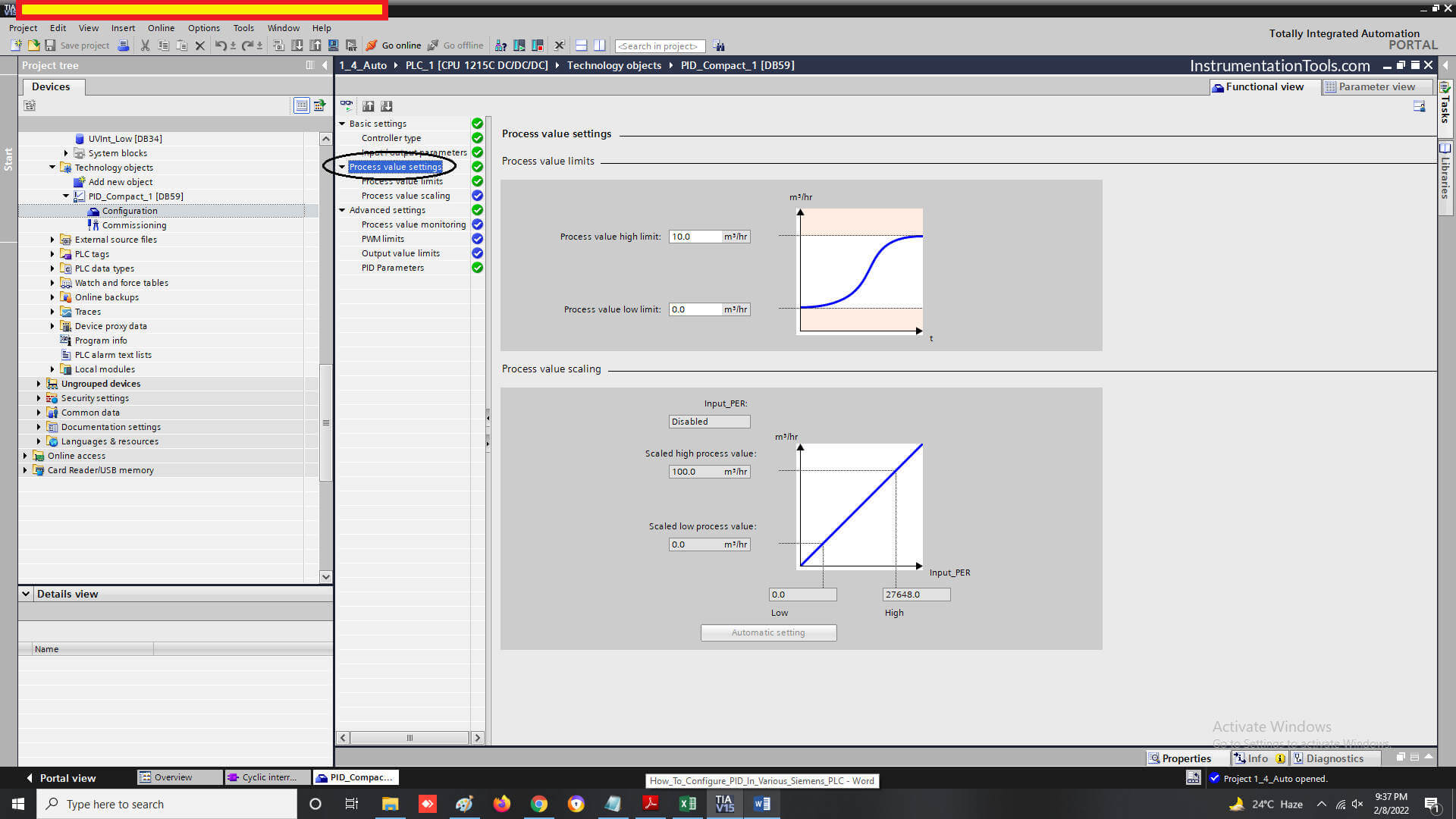
In the process value settings screen, as shown in the second image, you have to select process value high limit and low limit.

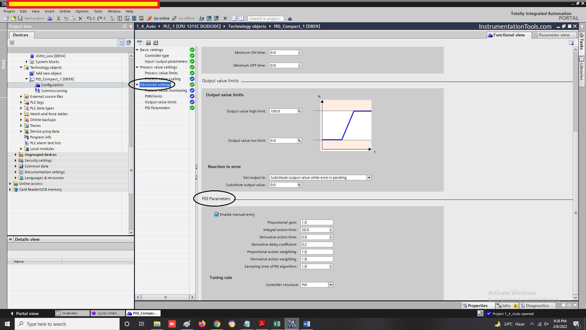
In the advanced settings screen, as shown in the third image, you have to set PID values (if you are not setting PID configuration to auto-tune).

Then, you have to add an OB (Cyclic Interrupt) in the program as shown in the figure.

Example of PID Control Instruction
How is PID programmed in Siemens S7
Siemens TIA PID

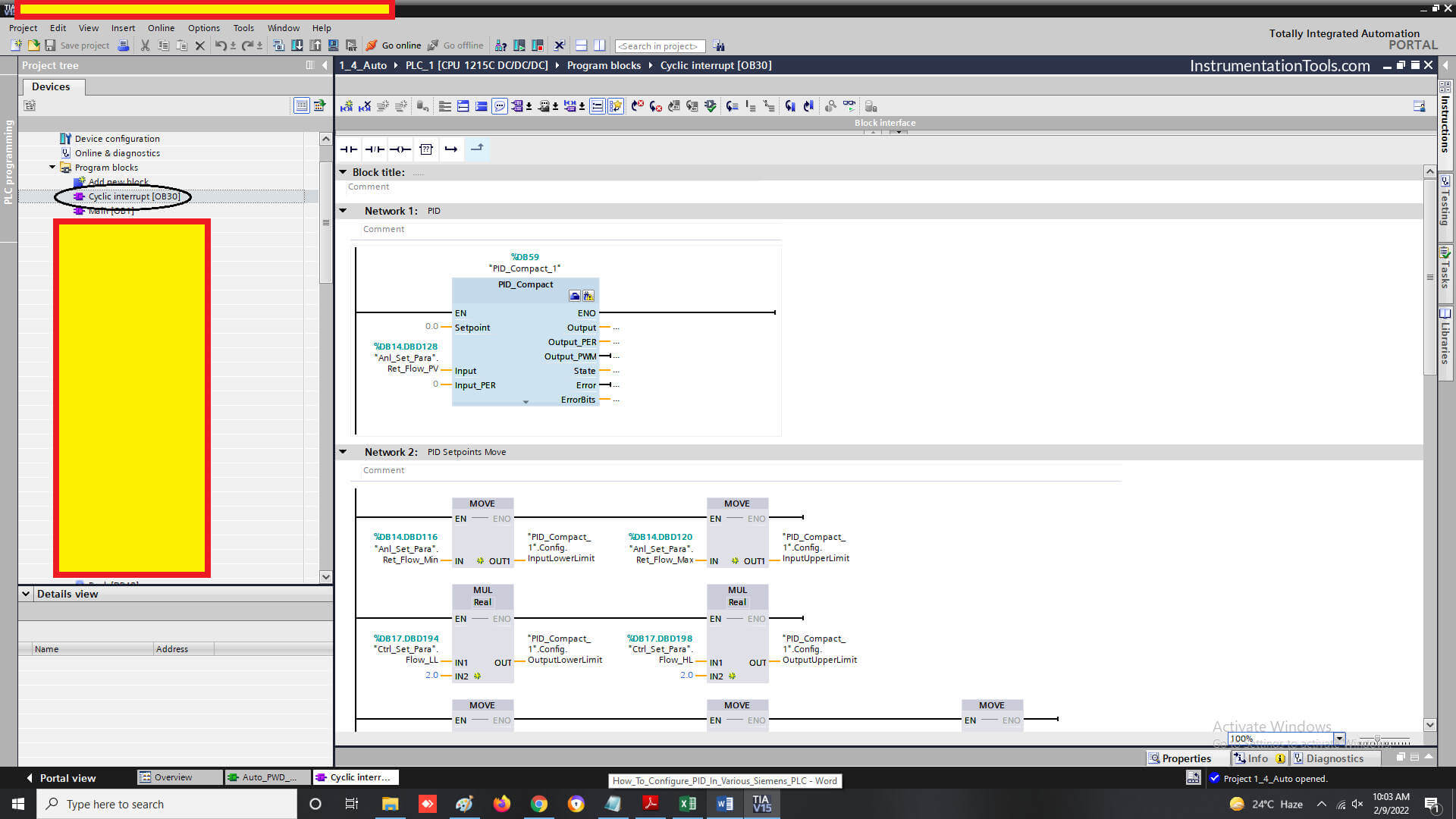
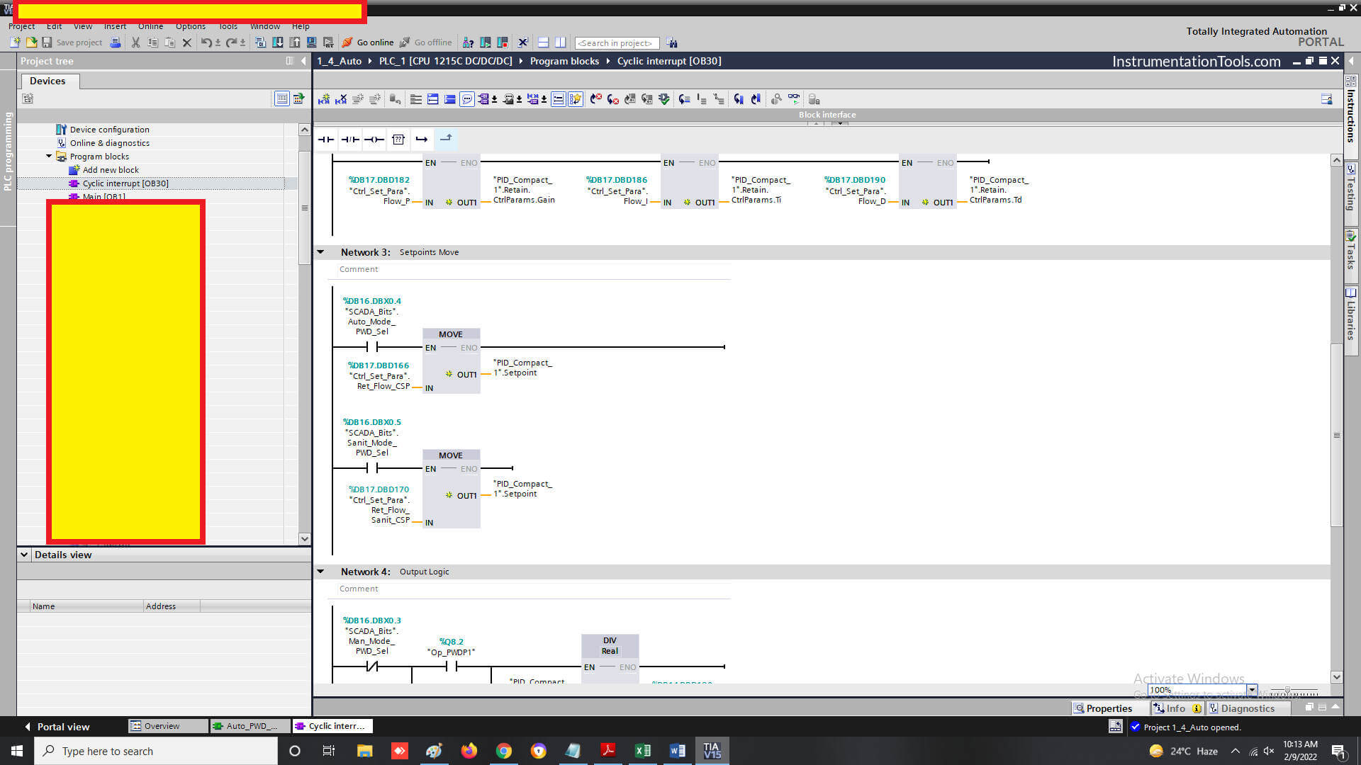
Then, as shown in the above three figures, you have to make the same sections in this OB.

Basically, you are moving set parameters from the HMI or SCADA in the PID configuration. This will overwrite the settings done in the PID configuration.

As shown, in the first image, take the PID block and map the process variable to it. Then, move the following parameters to the PID configuration – input lower and upper limits, output lower and upper limits, P, I, D, and control set-point.

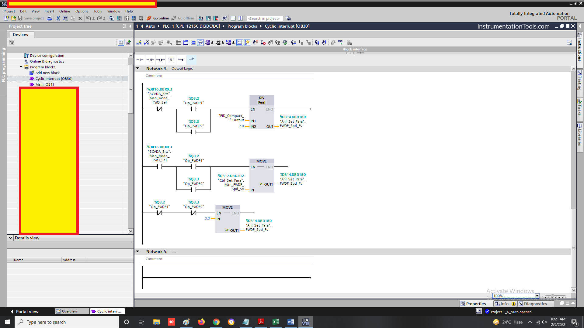
In the third image, we have to only move the PID output to the physical analog output according to the logic required.

After doing all this, just download the backup in PLC, power recycle it, and check. The PID will work properly according to the parameters set.

In this way, we saw how to configure PID in Siemens PLC.

Siemens Tia PLC Course

Follow the below series of videos from Siemens PLC Tia course.

Introduction to Siemens PLC - Free Tia Portal Training Course

If you liked this article, then please subscribe to our YouTube Channel for Electrical, Electronics, Instrumentation, PLC, and SCADA video tutorials.

You can also follow us on Facebook and Twitter to receive daily updates.

Read Next:

  • Nameplate of a Motor
  • Solenoid-controlled Valve
  • MODBUS ASCII Communication
  • DCS Alarm Summary Dashboard
  • AC Fundamentals Questions
Don't Miss Our Updates
Be the first to get exclusive content straight to your email.
We promise not to spam you. You can unsubscribe at any time.
Invalid email address
You've successfully subscribed !

Continue Reading

What is Human Machine Interface (HMI) ?
How to Create Templates in FactoryTalk View Studio?
How to Convert Voltage to Current using Resistor ?
Tia Portal – Different Instances of Calling a Function Block
Traffic Lights Ladder Diagram using Timers
4-20 mA Transmitter Wiring Types : 2-Wire, 3-Wire, 4-Wire
Share This Article
Facebook Whatsapp Whatsapp LinkedIn Copy Link
Share
Leave a Comment

Leave a Reply Cancel reply

Your email address will not be published. Required fields are marked *

Stay Connected

128.3kFollowersLike
69.1kFollowersFollow
210kSubscribersSubscribe
38kFollowersFollow

Categories

Explore More

PLC Programming Course Online Free
PLC Programming Example on Timers Function Block
Instrumentation Earthing
How to Wire a Field instrument to Control Room with Example
Flip-Flop PLC Programming: Lights with Adjustable Timers
Car Parking System using PLC Programming
How to Choose a Suitable HMI for Your Application?
PLC Ladder Logic Example based on Set Coil and Reset Coil

Keep Learning

Difference Between Microcontroller and PLC

Difference Between Microcontroller and PLC

Yokogawa DCS Tutorials - Configuration of Analog Input (Transmitter)

Yokogawa DCS Tutorials – Configuration of Analog Input (Transmitter)

PLC Motor Control Circuit-3

Basics of PLC Programming

Relay Permissive and interlock circuits

Basics of Permissive and Interlock Circuits

Automatic Liquid Mixing Application

PLC Program for Automatic Liquid Mixing Application

TON Timer in RSlogix

Why is RTO used in the Place of TON Timer?

How to Select the Right Encoder for Your Machine

How to Select the Right Encoder for Your Machine?

PLC Project Examples for EcoStruxure Machine Expert

PLC Project Examples for EcoStruxure Machine Expert

Learn More

electrical-drives-questions-answers

Electrical Drives Questions & Answers

Control Systems Questions & Answers

Control Systems Objective Questions & Answers – Set 6

Paddle Wheel Flow Meter

Paddle Wheel Flow Meters – Principle, Advantages, Limitations

Industrial Flame Detectors

Industrial Flame Detectors

Specific-Conductance-Calibration-Procedure

Specific Conductance Calibration Procedure

Why Fire and Gas Detectors are 3-Wire types instead of 2 Wire

Why Fire and Gas Detectors are 3-Wire types instead of 2 Wire?

Series - Wound DC Motor

Series-Wound Motor

DCS Marshalling Cabinet

The Purpose of Marshalling Cabinet or Marshalling Panel

Menu

  • About
  • Privacy Policy
  • Copyright

Quick Links

  • Learn PLC
  • Helping Hand
  • Part Time Job

YouTube Subscribe

Follow US
All rights reserved. Reproduction in whole or in part without written permission is prohibited.
Welcome Back!

Sign in to your account

Username or Email Address
Password

Lost your password?