In this article, we will be discussing the function of forcing and modifying in the PLC programming and its effects on the Siemens program logic.
Forcing and Modifying is the software facility (feature) that works differently in s7- 300 and s7- 400 PLCs.
In the process industries, processes run for long hours 24×7 365 days, in such a situation if any fault occurs then the whole process interrupts or stops depends on the criticality of the fault occurs.
Now let us consider that there is a fault in the pump (say some failure) and unable to run the pump. Due to this fault, PLC won’t allow other processes to run (as depends on pump run feedback), in such condition we can force the feedback of the pump to ON, so PLC understands that there is no fault now and allow other processes to complete the task. (Take all precautions before forcing logics, if we do forcing without cross-checking then it may lead to equipment failure or production loss)
In our example, there is some failure in the pump, so it is not starting. Because of this we are not receiving the pump run feedback. Say, we have a situation that, we want to run the remaining process even though the pump may not run but this remaining process runs only when we receive this pump run feedback. So now we are forcing the pump run feedback, thus making the PLC believe that the pump is running in the field by forcing. In actual condition, the pump is not running.
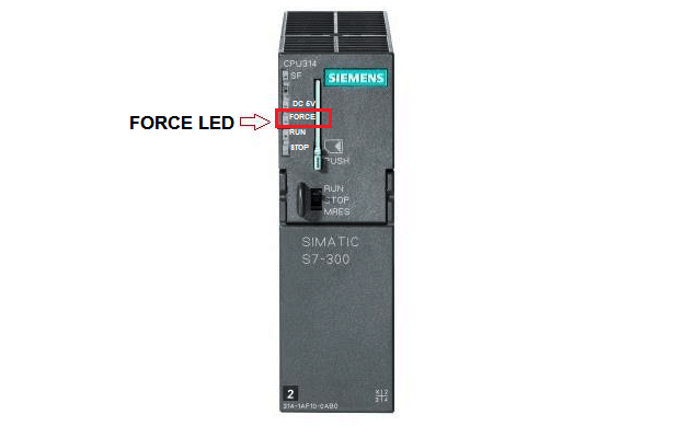
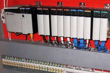
Now question is that how we get to know that someone has a force input or output? You can see in the above figure of CPU of siemens, it has a LED indication with label “FORCE”. Whenever this LED is ON means inputs or outputs forced in the logic.
Forcing versus Modifying
Let’s discuss some of the differences between forcing and modifying :
1. For force, there is LED indication is available on CPU whereas there is no such thing available for modifying.
2. To do force, you have to connect PC with PLC, now after forcing any facility, if you disconnect PC from PLC forcing will remain active whereas in modifying if you disconnect PC from PLC we lost all the modifications we have done.
3. While working on forcing, if you lost power all the changes you have done will remain the same but in modifying you lost everything which you have modified.
4. We can only force input, output in s7-300 and s7-400 PLCs and can force memory in s7-400 PLCs but we can’t force timer, counter and data blocks whereas in modifying we can modify everything which is above stated.
Forcing in Siemens PLC
— Now let learn where to find forcing facility in siemens PLCs. —
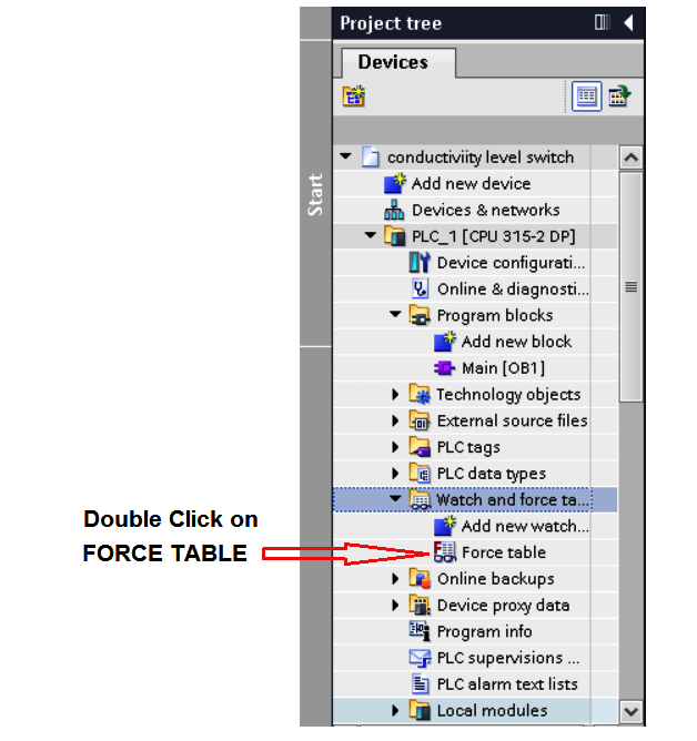
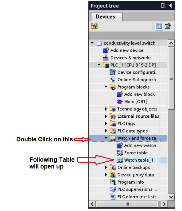
1. In the project tree Go to “watch and force table” and double click on the “force table”.
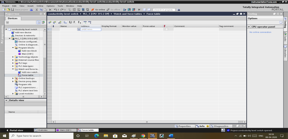
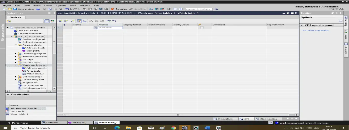
2. The following window will popup.
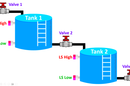
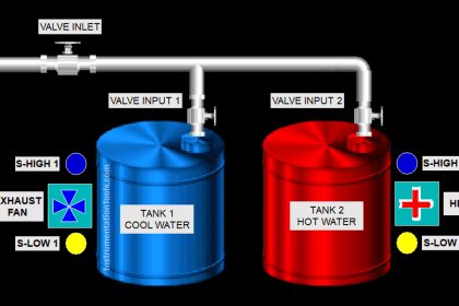
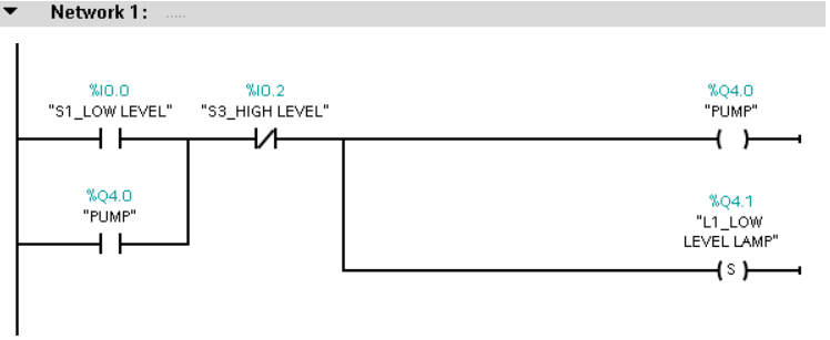
Here let us take our old program of conductivity level switch we are going to force one of the output here.
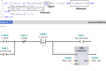
Here we will use one of the networks of our program.
I am going to force the PUMP. So in the above window, you can see there is an address section where I will put an address of the PUMP.
3. As shown in the below window you can see I have to enter the address of the pump.
Now write “TRUE” in the force value table then click on the below shown icon to activate forcing.
One thing to note that we must connect your PC with PLC to make things work. In forcing you only can connect by staying online with actual PLC connected with it, you can’t force it with the simulator.
Modifying in Siemens PLC
Now let’s talk about how to use modifying.
In modifying it works like forcing but we all know what difference is between them.
To open modify facility,
1. in the project tree Go to “watch and force table” double click on it and a new icon named “watch table_1” will be generated.
2. By clicking on “watch table_1” the following window will popup.
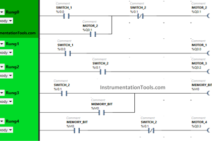
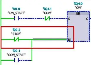
Let consider the following example of a motor control program as shown in the figure, one of the connections of the stop button gets to loosen up or disconnected. Here STOP button is NC due to that reset button stays active which won’t allow the motor to run.
Now due to a problem, we don’t want to stop the whole process. By connecting PC to PLC we can easily modify it to run till maintenance personnel solve this issue.
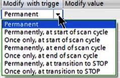
3. As you can see in the below window you can modify the value to make it TRUE. If the maintenance process is a bit longer then we have to modify it for “permanent” rather then to select for one scan cycle.
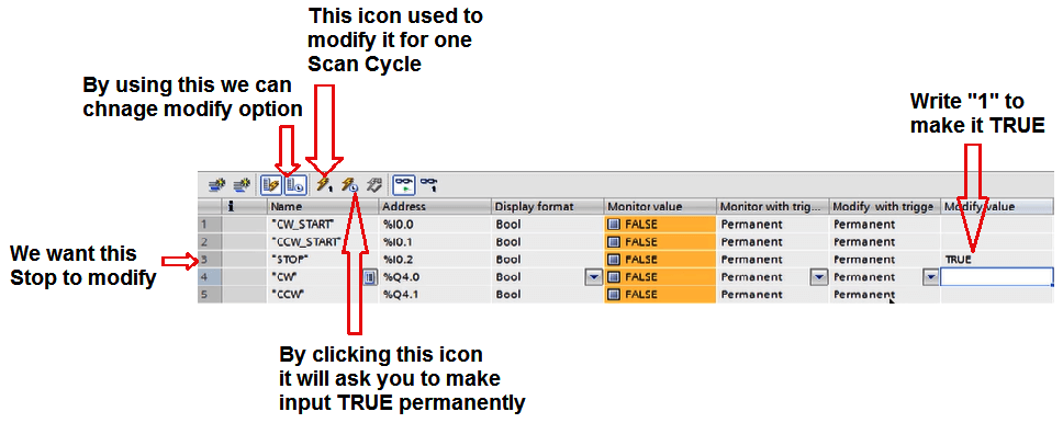
4. In “modifying with the trigger” you can set when you want to set your input or output to stay ON and for how much time you want to make it ON.
In modifying we can modify a value in simulator and PLC.
Author: Suhel Patel
If you liked this article, then please subscribe to our YouTube Channel for PLC and SCADA video tutorials.
You can also follow us on Facebook and Twitter to receive daily updates.
Read Next:
- Ladder Logic Examples
- PLC, HMI, VFD, and Motor
- Pulse Generation using Timer
- Liquid Mixing PLC Logic
- Two Hand Control Logic