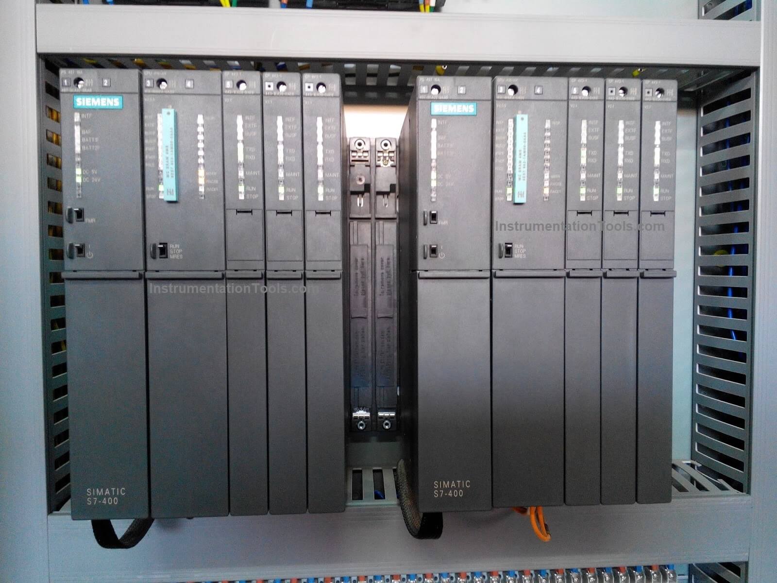
Except for their high prices, we can say that “SIEMENS S7-400 PLC” is one of the best PLCs in the Automation field; almost any automation task can be implemented with a suitable choice of S7-400 components.
One of its best advantages is that its modules have a block design for swing mounting in a rack. Expansion racks are available to extend the system also.
So, today we are going to discuss the various types of Racks in a PLC that could be implemented with these devices and we will clarify the differences between all of them.
The function of Racks for a PLC System
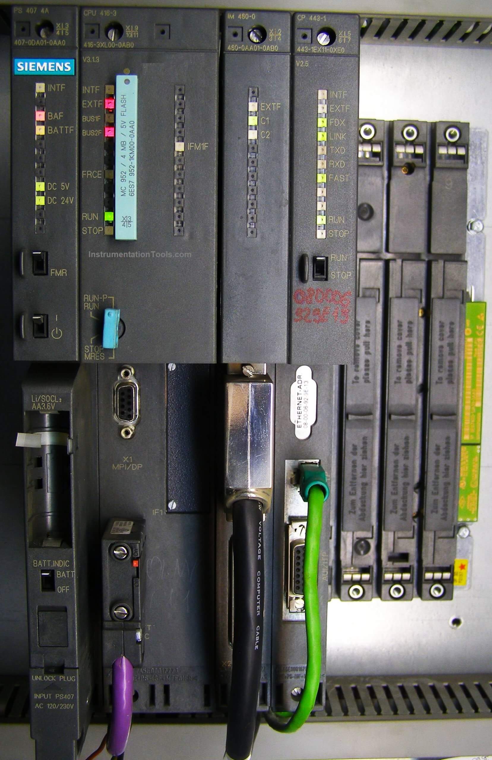
The rack serves as the backbone of the modular PLC system that holds all the modules together such as the CPU, Power Module, Communication Module, Input-Output Modules, etc.
In addition, PLC Rack synchronizes both the power and communication signal to all the modules.
A PLC Rack can be of different sizes and shapes depending upon the requirement of the control system.
Smaller PLC systems often contain all of the components into one compact housing (often referred to as a shoebox or brick).
Briefly, we can say that racks provide the electrical and mechanical connections between the PLC modules.
S7-400 PLC Racks
The racks in the PLC do the following tasks:
- They hold the modules.
- They supply the modules with operating voltage.
- They connect the individual modules to each other via the signal buses.
The backplane bus of the rack consists of two different bus systems:
- Input / Output (I/O) bus: this is a parallel backplane bus designed for the fast interchange of I/O signals. Each rack has an I/O bus. Time-critical operations to access the process data of the signal modules take place via the I/O bus.
- Communication (C) bus: this is a serial backplane bus designed for the fast exchange of large volumes of data parallel to the I/O signals. Except for racks ER1 and ER2, each rack has a communication bus.
Types of S7-400 PLC Racks
An S7-400 programmable controller consists of a Universal rack (UR), a Central Rack (CR), and one or more Expansion Racks (ERs), as required.
Central Racks (CR)
The rack containing the CPU is known as the central rack (CR). The racks containing modules in the system and connected to the CR are the expansion racks (ERs).
Segmented Central Racks
Notice that there are two types of central racks “segmented & non-segmented”.
In the (non-segmented) CR, the I/O bus is continuous and interconnects all 18 or 9 slots however, in the segmented CR; the I/O bus consists of two I/O bus segments.
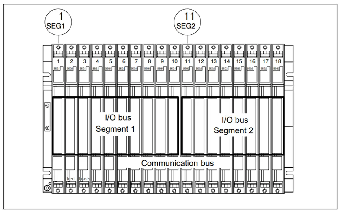
The Rack CR2; (6ES7401-2TA01-0AA0)
The CR2 rack is used for assembling segmented central racks. The CR2 has both an I/O bus and a communication bus.
The I/O bus is split into two local bus segments with 10 or 8 slots.
Technical Specification for (CR2)
| Rack | CR2 |
| Number of single-width slots | 18 |
| Dimensions W x H x D (in mm) | 18 482.5 x 290 x 27. |
| Weight | 3 kg 4.1 as of version 03 |
| Busses | Segmented I/O bus, continuous communication bus |
| Only one power supply module |
The Rack CR3; (6ES7401-2TA01-0AA0)
The CR3 rack is used for the assembly of CRs in standard systems (not in fault-tolerant systems). The CR3 has an I/O bus and a communication bus.
Technical Specification for (CR2)
| Rack | CR3 |
| Number of single-width slots | 4 |
| Dimensions W x H x D (in mm) | 122.5 x 290 x 27.5 |
| Weight | 0.75 Kg |
| Busses | I/O bus and continuous communication bus |
Subdivided Central Racks
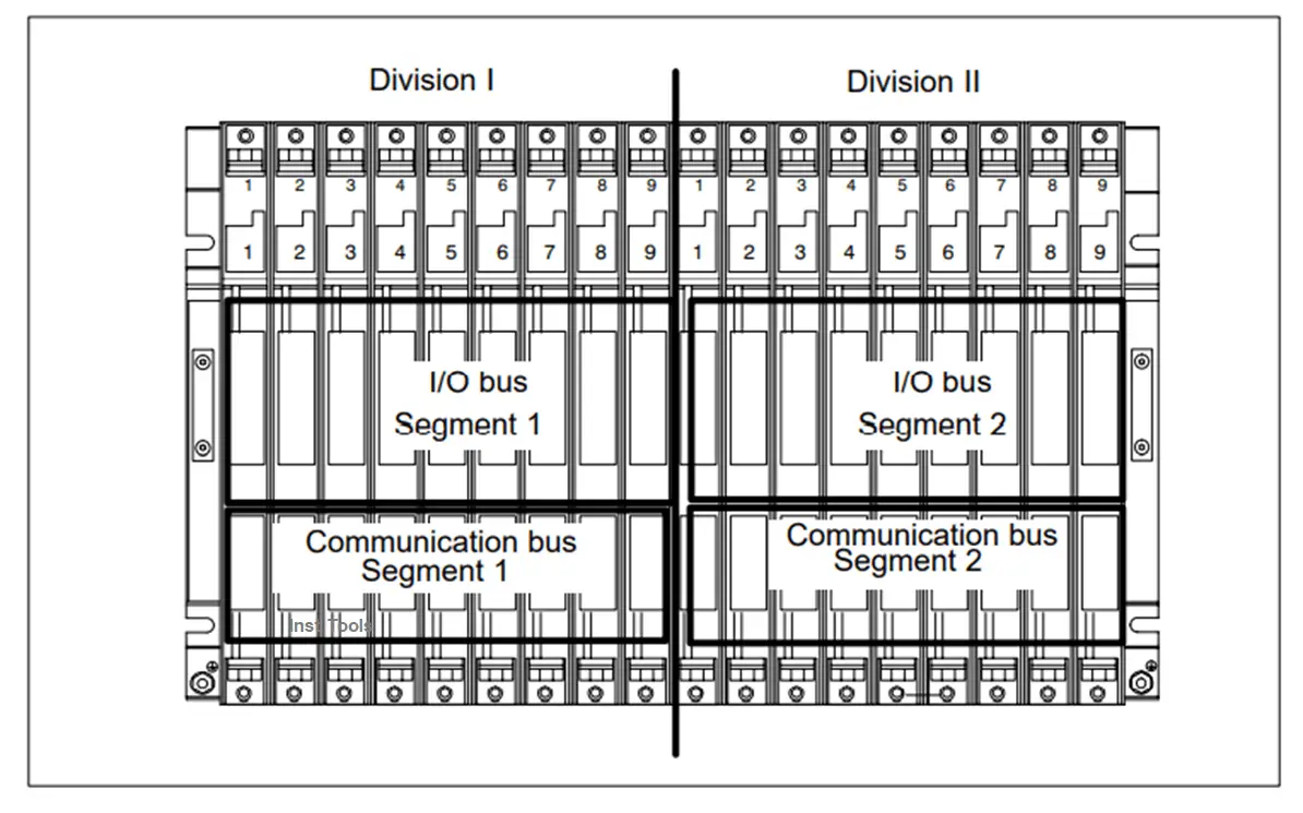
The “subdivided” characteristic relates to the configuration of the CR. In the (non-divided) CR, the I/O bus and communication bus are continuous and interconnect all the slots; in the subdivided CR, however, the I/O bus and communication bus consist of two segments each.
The UR2-H rack used here functions as two electrically isolated UR2 racks on the same rack profile.
A subdivided CR has the following important characteristics:
- The communication bus and I/O bus are subdivided into two segments with 9 slots each.
- Each segment represents a self-contained CR.
Expansion Racks (ER)
You can add ERs to compensate for the lack of slots for your application or operate signal modules at remote locations.
When using ERs, you need interface modules (IMs) as well as additional racks, and additional power supply modules if necessary. When using interface modules, you must always use the appropriate partners: you insert a send IM in the CR, and the matching receive IM in each connected ER.
You can connect up to 21 ERs of the S7-400 to one CR. In addition, the ERs are assigned numbers to identify them.
Technical Specification for (ER1, ER2)
| Rack | ER1 | ER2 |
| Number of single-width slots | 18 | 9 |
| Dimensions W x H x D (in mm) | 482.5 x 290 x 27.5 | 257.5 x 290 x 27.5 |
| Weight | 2.5 3.8 as of version 03 | 1.25 2.0 as of version 03 |
| Busses | Restricted I/O bus | Restricted I/O bus |
Universal Racks (UR)
The UR1 and UR2 racks are used for assembling central racks and expansion racks. The UR1 and UR2 racks have both an I/O bus and a communication bus.
The Racks UR1; (6ES7400-1TA01-0AA0) and UR2; (6ES7400-1JA01-0AA0)
You can use the following modules in the UR1 and UR2 racks:
- When the UR1 or UR2 is used as a central rack:
All S7-400 modules with the exception of receiving IMs
- When the UR1 or UR2 is used as an expansion rack:
All S7-400 modules with the exception of CPUs and send IMs
Technical Specification for (UR1, UR2)
| Rack | UR1 | UR2 |
| Number of single-width slots | 18 | 9 |
| Dimensions W x H x D (in mm) | 482.5 x 290 x 27.5 | 257.5 x 290 x 27.5 |
| Weight | 3 4.1 as of version 03 | 1.5 2.15 as of version 04 |
| Busses | I/O bus and communication bus | I/O bus and communication bus |
The Rack UR2-H; (6ES7400-2JA00-0AA0)
The UR2-H rack is used for assembling two central racks or expansion racks in one rack. The UR2-H rack essentially represents two electrically isolated UR2 racks on the same rack profile.
The main area of application of the UR2-H is in the compact structure of redundant S7-400H systems (two sub racks or subsystems in one rack).
Technical Specification for (UR1, UR2)
| Rack | UR2-H |
| Number of single-width slots | 2 * 9 |
| Dimensions W x H x D (in mm) | 482.5 x 290 x 27.5 |
| Weight | 3 4.1 as of version 03 |
| Busses | Segmented I/O bus, segmented communication bus |
Resources
- Automation System S7-400
Hardware and Installation
Installation Manual
- S7-400, M7-400 Programmable Controllers
Module Specifications
If you liked this article, then please subscribe to our YouTube Channel for Instrumentation, Electrical, PLC, and SCADA video tutorials.
You can also follow us on Facebook and Twitter to receive daily updates.
Read Next:
- What is a Wet Contact?
- How to Select a SCADA?
- Redundancy in Siemens PLC
- Allen Bradley PLC Hardware
- Motor Classic Control Circuits