Inst ToolsInst ToolsInst Tools
  • Courses
  • Automation
    • PLC
    • Control System
    • Safety System
    • Communication
    • Fire & Gas System
  • Instrumentation
    • Design
    • Pressure
    • Temperature
    • Flow
    • Level
    • Vibration
    • Analyzer
    • Control Valve
    • Switch
    • Calibration
    • Erection & Commissioning
  • Interview
    • Instrumentation
    • Electrical
    • Electronics
    • Practical
  • Q&A
    • Instrumentation
    • Control System
    • Electrical
    • Electronics
    • Analog Electronics
    • Digital Electronics
    • Power Electronics
    • Microprocessor
  • Request
Search
  • Books
  • Software
  • Projects
  • Process
  • Tools
  • Basics
  • Formula
  • Power Plant
  • Root Cause Analysis
  • Electrical Basics
  • Animation
  • Standards
  • 4-20 mA Course
  • Siemens PLC Course
Reading: Basics of Sight Glass Level Gauge
Share
Notification Show More
Font ResizerAa
Inst ToolsInst Tools
Font ResizerAa
  • Courses
  • Design
  • PLC
  • Interview
  • Control System
Search
  • Courses
  • Automation
    • PLC
    • Control System
    • Safety System
    • Communication
    • Fire & Gas System
  • Instrumentation
    • Design
    • Pressure
    • Temperature
    • Flow
    • Level
    • Vibration
    • Analyzer
    • Control Valve
    • Switch
    • Calibration
    • Erection & Commissioning
  • Interview
    • Instrumentation
    • Electrical
    • Electronics
    • Practical
  • Q&A
    • Instrumentation
    • Control System
    • Electrical
    • Electronics
    • Analog Electronics
    • Digital Electronics
    • Power Electronics
    • Microprocessor
  • Request
Follow US
All rights reserved. Reproduction in whole or in part without written permission is prohibited.
Inst Tools > Blog > Level Measurement > Basics of Sight Glass Level Gauge

Basics of Sight Glass Level Gauge

Last updated: September 2, 2019 4:51 pm
Editorial Staff
Level Measurement
No Comments
Share
4 Min Read
SHARE

Level gauges are perhaps the simplest indicating instrument for liquid level in a vessel. They are often found in industrial level-measurement applications, even when another level-measuring instrument is present, to serve as a direct indicator for an operator to monitor in case there is doubt about the accuracy of the other instrument.

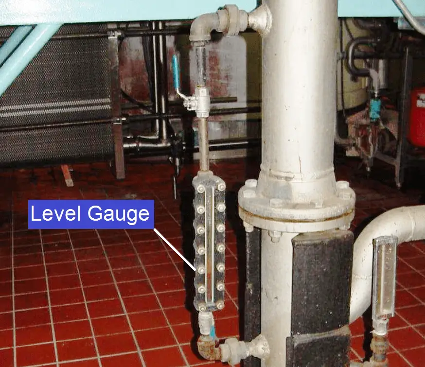
The level gauge, or sightglass is to liquid level measurement as manometers are to pressure measurement: a very simple and effective technology for direct visual indication of process level. In its simplest form, a level gauge is nothing more than a clear tube through which process liquid may be seen. The following photograph shows a simple example of a sightglass:

level gauge

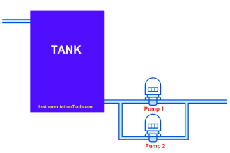
A functional diagram of a sightglass shows how it visually represents the level of liquid inside a vessel such as a storage tank:

What is a level gauge

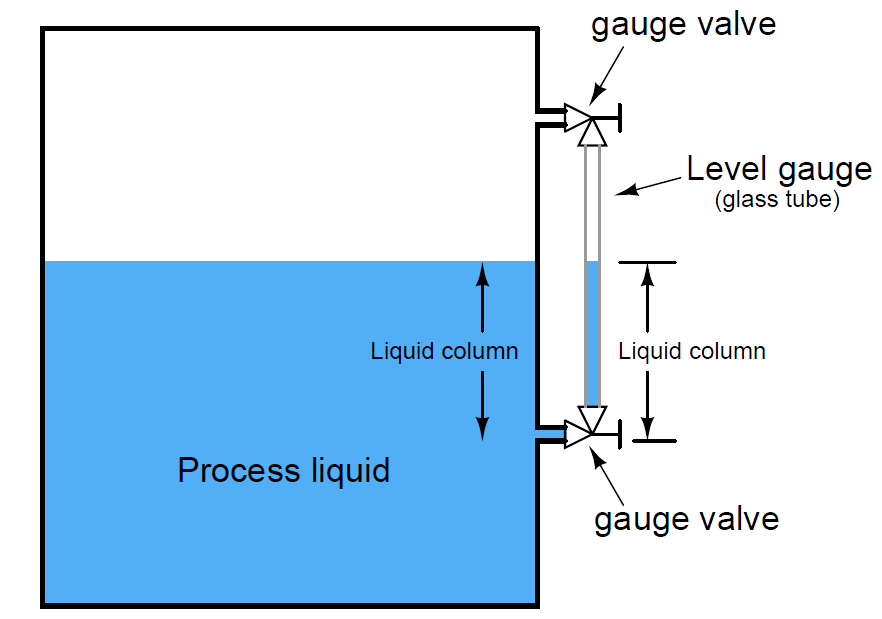
A level gauge is not unlike a U-tube manometer, with equal pressures applied to both liquid columns (one column being the liquid in the gauge sightglass, the other column being the liquid in the vessel).

Level gauge valves exist to allow replacement of the glass tube without emptying or depressurizing the process vessel. These valves are usually equipped with flow-limiting devices in the event of a tube rupture, so too much process fluid does not escape even when the valves are fully open.

Some level gauges called reflex gauges are equipped with special optics to facilitate the viewing of clear liquids, which is problematic for simple glass-tube sightglasses.

A weakness of glass-tube level gauges is the glass tube itself. The tube must be kept in a clean condition in order for the liquid level to be clearly visible, which may be a problem in a dirty-liquid service. Also, glass tubes may rupture if subjected to thermal or mechanical shock. One solution to this problem is to eliminate the glass tube entirely, replacing it with a non-magnetic metal tube (e.g. stainless steel) containing a magnetized float, with magnet-sensing indicator flags outside of this tube to visually indicate level. Here is one example of such a level gauge :

glass-tube level gauges

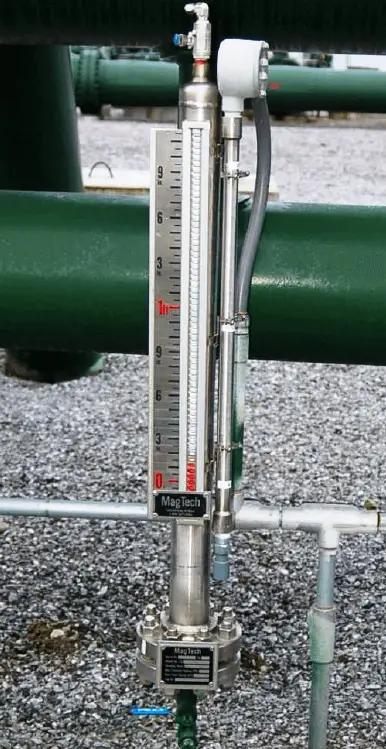
In this instrument, you can see red-colored flags toward the bottom of the scale which have been “flipped” by the motion of the magnetic float inside the stainless-steel tube. The height of the red zone (i.e. how many flags have been flipped to show their red sides) indicates the height of the liquid inside the tube.

Some magnetic level gauges even have high- and low-level magnetic switches located at strategic points along the tube’s height, providing discrete sensing capability for alarms and/or shutdown controls, if the liquid level ever goes outside of safe operating limits. These switches will open and close as the magnetic float passes by, remotely signaling liquid level at that height.

 Credits : Tony R. Kuphaldt – Creative Commons Attribution 4.0 License

Don't Miss Our Updates
Be the first to get exclusive content straight to your email.
We promise not to spam you. You can unsubscribe at any time.
Invalid email address
You've successfully subscribed !

Continue Reading

Open and Closed Tank Level Calculations
Nuclear Level Detectors Cascade or Master/Slave concept
Contact and Non-Contact Level Sensors
Guided-Wave Radar Instruments Diagnostics
Practical Level Sensors Questions and Answers
Non-Contacting Radar Level Transmitter Working Principle
Share This Article
Facebook Whatsapp Whatsapp LinkedIn Copy Link
Share
Leave a Comment

Leave a Reply Cancel reply

Your email address will not be published. Required fields are marked *

Stay Connected

128.3kFollowersLike
69.1kFollowersFollow
210kSubscribersSubscribe
38kFollowersFollow

Categories

Explore More

DP Transmitter Dry Leg & Wet Leg Calculations
Overview of Tank Gauging Technologies
Open Tank Interface Level Measurement
What is a Submersible Pressure Transmitter? Principle, Advantages
How to Calculate mmWC Range of Level Transmitter with Examples?
Instruments Tapping Points – Common versus Individual
Magnetostrictive Tank Gauging (MTG)
Servo Operated Float Level Measurement

Keep Learning

DP Level Measurement Problems

DP Level Measurement Problems

Open-Tank-DP-Level-Transmitter-with-Zero-Suppression-Calibration

DP Level Transmitter with Zero Suppression Calibration

Sounding Level Transmitter Working Animation

Tilt Level Switch Theory

Tilt Level Switch Working Principle

Level Measurement using DP Transmitters - Open Tank

Open Tank Level Measurement using DP Transmitters Animation

Closed Tank DP Level Transmitter

How to Find LRV and URV of Closed Tank DP Level Transmitter

Tank Gauging Measurement

Effect of Tank Design on Accuracy of Level Measurement

Level Gauge Theory

Types of Level Gauges

Learn More

Avoid Process Downtime With Five Device Protection Considerations

How to Avoid Process Downtime ?

In this article, you will learn the configuration of PlantPAx library in factory talk studio of Rockwell Automation.

Configuration of PlantPAx Library in Factory Talk Studio

WHILE DO Statement in SCL Language

WHILE DO Statement in SCL Language

Industry 4.0 Explained

Industry 4.0 Explained – Industrial Internet of Things

Transmitter Indicators

What is Indicator ?

CNC Machining Glass Industry

5 Ways CNC Machining is Benefiting the Glass Industry

Difference Between LDR and Photodiode

Difference Between LDR and Photodiode

Allen-Bradley MicroLogix PLC Wiring

Programmable Logic Controller (PLC) Questions and Answers – 8

Menu

  • About
  • Privacy Policy
  • Copyright

Quick Links

  • Learn PLC
  • Helping Hand
  • Part Time Job

YouTube Subscribe

Follow US
All rights reserved. Reproduction in whole or in part without written permission is prohibited.
Welcome Back!

Sign in to your account

Username or Email Address
Password

Lost your password?