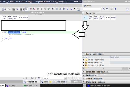
This is a PLC Program for a fan control unit system for industry. Learn the PLC ladder diagrams with example problems.
PLC Programming for Fan Control Unit
There are three fans in a system. During the system running two fans must be running out of three fans.
Implement the logic for the fan control unit in PLC using the ladder diagram programming language.
Problem Diagram

Problem Solution
- We will use PLC S7-300 for this application.
- In this system, there are three fans (fan1, fan2 and fan3)
- During system running any two fans out of three must be running. To start any two fans – say fan 2 and fan 3 – individual start & stop buttons are provided for each.
- Suppose fan 2 and fan 3 are running and one of them becomes faulty then fan 1 should be ON automatically i.e. at any given point of time two fans should be running.
- If there is a fault with any two fans then incoming supply to the system should be switched OFF automatically.
- The ‘ON’ status of the fans and also the status of main supply should be indicated by corresponding LED. If there is fault with more than one fan, indicate it as fault status with 5Hz flashing of LED.
- Fault with one fan or no fault with fan should be indicated by steady light on fault Status LED.
List of inputs and outputs
List of inputs
- Main switch :- I2.0
- Cycle START :- I0.0
- Cycle STOP :- I0.1
- Fan 1 fault :- I1.0
- Fan 2 fault :- I1.1
- Fan 3 fault :- I1.2
List of outputs
- Fan 1 :- Q0.0
- Fan 2 :- Q0.1
- Fan 3 :- Q0.2
- Fault indication :- Q0.3
- Fan 1 ON indication :- Q0.4
- Fan 2 ON indication :- Q0.5
- Fan 3 ON Indication :- Q0.6
- Main supply ON indication :- Q0.7
M memory
- Cycle ON :- M0.0
- 5HZ clock pulse :- M0.5
Ladder Diagram for fan control unit


Program Description
For this application, we used S7-300 PLC and TIA portal software for programming.
Network 1:
We used latching circuit for cycle ON (M0.0) coil. It can be started by pressing START PB (I0.0) and stop by pressing STOP PB (I0.1). Main switch (I2.0) must be ON.
Network 2:
When cycle is ON (M0.0) and fan 2 and fan3 faults are not present, fan2 (Q0.1) and fan 3(Q0.2) will be ON.
Network 3:
Either Fan 2 or Fan 3 is faulty, fan 1 will be activated (Q.0).
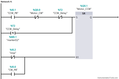
Network 4:
In system if any two fans out of three are faulty, fault indication lamp (Q0.3) will begin flickering with 5HZ frequency.
Network 5:
Indication lamps for fan 1, fan 2 and fan 3.Lamp will be activated according to fault signal.
Network 6:
When main switch is ON (I2.0), main supply ON indication lamp (Q0.7) will be ON.
Note :- Above application may be different from actual application. This example is only for explanation purpose only. We can implement this logic in other PLC also. This is the simple concept of fan control unit used in industry, we can use this concept in other examples also.
All parameters considered in example are for explanation purpose only, parameters may be different in actual applications. Also all interlocks are not considered in the application.
Result

Author: Bhavesh
If you liked this article, then please subscribe to our YouTube Channel for PLC and SCADA video tutorials.
You can also follow us on Facebook and Twitter to receive daily updates.
Read Next:
- Basics of PLC Programming
- PLC Star Delta Motor Starter
- RSLogix 5000 PLC Programming
- Temperature Control using Thermostat
- PLC Analog Input Conversion Formula


Sir can you suggest any simulator software for s7 300 plc. So that young aspirants can practice all these helpful program sections.
good