An instrument air supply and conditioning system consist of components required to provide an adequate volume of instrument quality air at the desired pressure.
Instrument Air Supply System
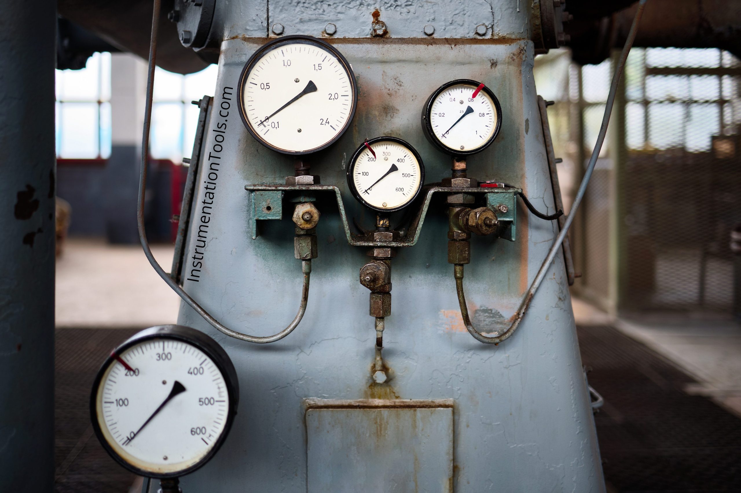
Typical components of the air supply system include the following:
- Filters
- Aftercoolers and moisture separators
- Compressors
- Pressure regulators
- Air treatment systems
- Pressure-relief devices
- Air receivers
- Piping
- Drain traps
Filters
A dry cartridge intake filter should be provided for the compressor in accordance with the manufacturer’s recommendations.
Filters should be located so they are readily accessible for maintenance.
Compressor
Compressors should be sized to deliver air at the specified pressure under all conditions, plus a margin for future demand and leakage.
Types of Compressor
Various types of compressors are available including the following:
- Reciprocating oiled piston
- Reciprocating oil-less piston
- Rotary vane
- Rotary liquid ring
- Diaphragm
- Rotary screw
- Centrifugal
Some compressors are lubricated internally by water, or by water with small amounts of soap or oil. Compressors identified as “unlubricated” do use lubrication for the bearings and working parts of the compressor, but the compressor chamber or cylinder is not lubricated because of the plastic or other low friction seals used on the piston eliminate the need for lubricating the cylinder walls.
The “diaphragm-type” compressor likewise is considered as being unlubricated because the compression chamber is separated from the lubricated portions of the compressor by a diaphragm.
Some compressors are identified as “oil-free” even though the compressor is internally oil-lubricated because filters are used. Filter limitations can allow lubricant carryover; therefore, “unlubricated” compressors are recommended.
Although not recommended, if lubricated compressors are used, lubricant removal is required to avoid the damaging effects on air system components and end-use devices. Provisions should be made to recover lubricants for disposal in accordance with national and local environmental requirements.
If synthetic oil is used to lubricate compressors, compatibility should be evaluated for end-use devices. For example, the effects of ester vapor released by synthetic oil can cause elastomeric damage to end-use devices.
AfterCooler and Moisture Separator
The aftercooler is a heat exchanger that cools the hot compressor discharge air below its dew point. The condensate is collected in a mechanical separator, which can remove 70 to 80 percent of the moisture and some particulate.
Moisture is typically drained by an automatic drain valve with a manual bypass or drip leg. This moisture should be removed from the air system to prevent equipment damage downstream.
Water-cooled aftercoolers are usually sized to cool outlet air to within 5°C (approximate) to 8°C (9°F to 15°F) of the inlet cooling water temperature.
Air-cooled aftercoolers are usually sized to cool outlet air to within 14°C to 17°C (25°F to 31°F) of the ambient air temperature.
Air Receiver
Air receivers should be sized to provide an adequate volume of air surge and allow for future growth. The air receiver surge time can be calculated. A pressure-relieving device should be installed as required by applicable local and national codes.
The receiver ambient temperature is typically lower than the dew point temperature of the air entering the receiver. This causes moisture to condense inside the receiver.
To help prevent condensate and particulate intrusion, the outlet line should be located near the top of the receiver and above the inlet line.
An automatic drain with a manual bypass should be located near the bottom of an air receiver to dispose of the condensate. Drains on a receiver are susceptible to plugging; therefore an ability to clean the lines should be provided.
Drain Taps
Automatic drain traps with manual bypasses should be located on receivers, airline drip-legs, inter-coolers, and after-cooler separator drain, as previously mentioned.
Trap failure indications such as level gauges, sight glasses, or alarms are recommended.
Air Treatment System
An instrument air treatment system consists of a pre-filter, an air dryer, and an after-filter.
Pre-filter
Coalescing pre-filters are required to limit liquids, oil, and water (in aerosol form) from entering the air dryers.
An automatic drain with manual bypass is recommended.
Air Dryer
Various types of dryers are available to remove moisture from compressed air. Selecting the proper type and size of the dryer should be based on the actual inlet flow conditions under which the dryer is expected to perform and on the quality of air that is to be produced.
Refrigerant dryers have limited applications due to dew point restrictions. If the design application allows the use of a refrigerant dryer, continuous monitoring is strongly recommended.
Dryer Selection Factors
The following factors should be considered when selecting dryers:
a) Maximum flow rate: m3/s (m3/h, SCFM)*
b) Maximum inlet temperature: °C (°F)
c) Maximum percentage moisture saturation of inlet (if unknown, assume inlet temperature at pressure dew point)
d) Minimum inlet pressure: kPa (psig)
e) Maximum inlet pressure: kPa (psig)
f) Maximum allowable outlet dew point temperature at dryer outlet pressure: °C (°F)
g) Required accessories (e.g., pressure gauges, relief valves, thermometers, timers, safety switches.
h) Other pertinent information, such as contaminants that may be present (oil, liquid, etc.)
i) Utilities available, such as electricity, steam, water, and control power
j) Electrical area classification where equipment is to be installed.
After Filter
After filters provide final cleaning of the air-stream by removing particulate matter from the dryer discharge. After-filters should be specified by absolute particle size.
After-filters are recommended on all instrument air systems and should be provided for desiccant dryers to prevent desiccant dust from passing downstream.
Heat reactivated dryers require high-temperature after-filters. For refrigerated dryers, coalescing filters are recommended.
Pressure Regulators
Pressure regulators are provided to control the pressure to downstream devices. Pressure regulator sizing and settings should be chosen such that each end-use device receives an adequate air supply.
Design review and installation of pressure-relieving devices should be considered, since pressure regulator failure will result in full system pressure on downstream system devices.
Pressure Relief Devices
Pressure relief devices should be installed in accordance with applicable codes and to protect devices from potential over-pressurization. Pressure relief devices may include self-relieving pressure regulators, rupture discs, and relief valves.
Check valves should be located and oriented, so they do not defeat the intended operation of the relief valves.
Relief valve settings should be high enough to avoid continuous lifting. The relief device setting should not exceed the design pressure rating of any device it protects.
Piping
Air distribution systems should be designed in accordance with local, national, and international codes and standards.
Air distribution systems should be designed to ensure that all end-use devices receive adequate air supply to ensure their satisfactory operation.
Discharge Piping
Piping between the compressor and the after-cooler, and the after-cooler separator and the air receiver, is considered to be discharge piping. This portion of the air system up to the air dryer will experience high moisture and high-temperature variations.
A corrosion-resistant pipe is recommended in systems using oil-free compressors. Unlike a lubricated compressor system, the piping lacks the oil film that protects the piping.
The corrosive effects are accelerated by the warm, moist air; vibration; pulsation; and temperature variations as compressors load and unload. The corrosion by-products lead to plugged lines, filters, and traps, and an increased corrosion rate can lead to premature wall failure.
When using carbon steel, an increased corrosion allowance should be used in calculating wall thickness for piping, valves, and vessels.
Branch Connections
The minimum pipe size for horizontal piping should not be less than 25 mm (1 inch) NPS, except when six-foot centered, horizontal piping supports are maintained, the minimum pipe size may be reduced to 15 mm (½ inch) NPS.
All branch takeoffs should be from the top of any horizontal piping header.
Manual Valves
The effects of moisture, lubricants, and particle contaminants on a valve’s internals should be considered. Flow rate and pressure drop should be considered when selecting the proper type of valve to use in each application.
Valves should be installed per the manufacturer’s recommendations and should be accessible for operation and maintenance.
Three basic types of valves are used commonly in instrument air distribution systems: globe, gate, and ball.
Globe Valves
The advantages of globe valves are that they provide the capabilities to regulate system flow rates and to provide tight shut-off.
Globe valves with a dial pointer or stem scales can be used to provide repeatable settings in a manual control mode.
Gate Valves
The advantages of gate valves are that they provide a full, line-size port for airflow with minimal pressure drop and are conducive to internal cleaning.
Gate valves typically are used for on/off isolation.
Ball Valves
The advantages of ball valves are that they provide a full, line-size port for airflow, with minimal pressure drop, and are conducive to internal cleaning.
Ball valves typically are used for on/off isolation.
Another advantage of ball valves is that they provide better shutoff than gate valves due to their elastomeric ball seal design.
Valve Location and Installation
The following should be considered to determine valve location and orientation:
a) Valves should be accessible from grade level or from personnel platforms.
b) Valves required to isolate or bypass a component should be located as close to the component as practical.
c) When globe or gate valves are used, rising-stem construction provides visual valve position.
d) Valve orientation should be per the manufacturer’s recommendations.
Read Next:
- Instrument Air Process Design
- Level Instruments Design
- Instrument Protection Seals
- Air Cylinder Consumption
- Instrument Air Compressor

