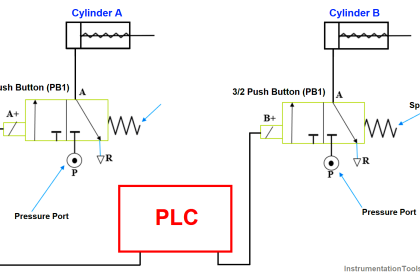
In this system a variable-frequency drive (VFD) sends AC electrical power to an induction motor to control the speed of that motor.
The VFD receives its “command” signal in the form of a 4-20 mA DC current sent from a programmable logic controller (PLC) with an analog output card, 4 mA representing a “zero-speed” signal (no power sent to the motor) and 20 mA representing a “full speed” signal (60 Hz power sent to the motor):
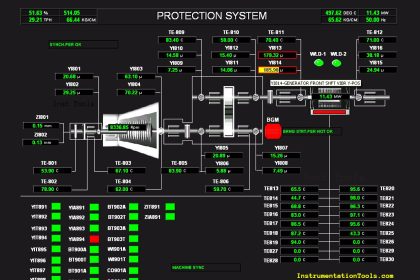
Problem on PLC HMI VFD
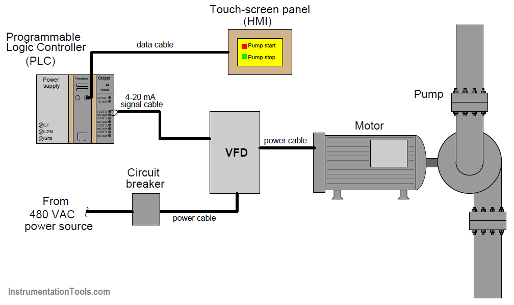
Unfortunately, though, there is something wrong with this system. The pump does not run, regardless of what the operator commands using the touch-screen panel. When you examine the VFD faceplate, you see a few LED indicators lit, but nothing either confirming or denying that power is reaching the motor.
Supposing the only test equipment available to you is a digital multimeter (DMM), what diagnostic tests could you perform to identify the location and nature of the system fault?
Share Your ideas on solving the problem with us through comments.
Scroll down to read the ideas shared by the users.
If you liked this article, then please subscribe to our YouTube Channel for PLC and SCADA video tutorials.
You can also follow us on Facebook and Twitter to receive daily updates.
Read Next:
- VFD Motor Speed Control
- What is Motor Jogging ?
- PLC Program for Running Hours
- JUMP Instruction in PLC
- Data Handling Instructions
- Ladder Logic Programming
Credits: Tony R. Kuphaldt


Hi, may I suggest that the whole power is to be shut down including its main switch, wait for 30seconds then restart by switching the main switch to on to enable the system restart
here is the steps to find out the cause
1. Need to Measure 3 phase supply is coming to VFD or not.
2. If 3 phase supply is available to VFD, need to turn on the motor through HMI , check 3 phase output is reaching to motor or not
3. If 3 phase output is reaching to motor then VFD is fine and something wrong with motor
4.If 3 phase output not reaching to motor then something wrong with VFD or power cables between VFD output terminal & motor input terminals
5. After tun the motor ON from HMI Check whether VFD output is giving output or not
6. If the VFD output is not giving output then something wrong wth VFD parameters settings
7. If VFD output is giving output & power not reaching it to motor then need to check power cables between VFD & motor.
Please am facing some challenge i have done all my checks and the output of the vfd is giving me power the parameter setting are all right but still the motor is not running on the vfd display settings can u help me with that
First I would use DMM to check if the VFD is getting it’s start signal from HMI, probably 120v from PLC digital output card.
If that is good I would then use the DMM to check VFD input for 4 to 20 ma. Need to make sure the 4 to 20 ma analog output card on PLC is good. Then I would use the DMM to check the fail to start relay to see if it is tripped.
If that is good I would use the DMM to check for 120 V at the motor starter relay. If the motor starter relay has voltage I would use DMM to check to see if 480 V is being applied to motor.
I would not use just a DMM as they do not draw enough current to test for a reliable source of supply. Use a “low impedance” setting on your DMM, or load the circuit with a resitor in parallel with the Voltmeter, say 5 000 Ohms. Loading the circuit will show up any poor connections.
Inspect for any error on VFD or HMI. If no alarm present.
Do following step.
1. Check incoming AC voltage using DMM at VFD panel.
2. Verify control loop for start and stop signal and speed input to VFD. If it is normal and all signal are recieving at VFD termination point then only thing to check is VFD settings and parameters.
1- 1st of all we must know if the enable signal reach the VFD or not either by DO from the PLC or by enable key in the VFD (according to your wiring).
2- For the 4-20ma you can check the VFD LCD you must find the equivalent HZ to this analog signal.
3- you must check VFD configurations such as the enable signal, run soure fixed speed or 4-20ma.
4- By the DMM you can check the 3 phase input voltage to the VFD if you found it and not found any voltage in the output of the VFD to the motor. So the problem in the VFD, and you must check by following the A/M points.
The output voltage and input voltages can be measured using the multimeter.we can know the faults with the power supply of there is any else there might be a problem with the output of the PLC it can be measured using the multimeter in DC voltage mode.
If any of these fails there might be a problem with PLC or the VFD itself.
Make sure polarity of 4-20 is correct. simple stuff first. then you can start trouble shooting the higher voltage.
First check analog o/p dcs coming 25% check mA, Note amps and check on command ofter all are ok main supply off wait some time after-on test all, check all interlocks healthy and control supply check.
as per my knowledge, its no longer helpful feeding a pump application motor by VFD, only DOL is more than enough though run by PLC & HMI
You need ON / OFF command (from PLC dgital output) to run VFD
With using a digital multimeter, I start checking the signals input in VFD coming from plc, if it greater than 4 mA I must check the vdf output to the motor, if there is no output voltage then I must check the setting of vfd
“Few LED indicators lit” … so 3 phase power input to VFD is OK
HIM : do start and stop
PLC : convert stop action to 4mA
and convert start to 20mA
VFD need ” START command ” as digital input signal on VFD terminal then mA analog signal (from PLC to VFD) will do START and STOP action
Solution : connect COM with START (jumber on terminal or use other method as 2-wire , 3-wire control
Precursor checks are only assumed here for a general explanation , ie pre-existing permits are checked for handover from different shifts/shutdown works/different trades maintenance,repairs, installation works.
Area and locations have been tested for gas for a safe working environment.
All permits to work have been gained before proceeding.
Checks with Control room chiefs/supervisors to ensure there are no upstream nor downstream interposing control isolations ie ESD events/ chemical reaction interventions nor air supply shutoffs nor process liquid diversion/blow offs to dump/drain/containment tank/reservoirs.
1) Physically Check pump is not turning/operating in the field to ensure no possibility of manually overridden/jammed/air leaks/locked off valves.
2)From VFD in MCC safe area, check the wiring connections are tight and that terminations correspond to loop diagrams.
3) check mains 415 voltage input from MCB to input terminals L1 L2 L3.
4) check output terminals of VFD (R S T U V W).
5) check and have second operative cycle through the 24vdc 4-20ma signalling via the HMI screen to ensure the corresponding 4-20ma signals reach the VFD terminals.
6) switch off lock off prove dead and prove test equipment is still working then proceed to disconnect outgoing field wiring to pump and use low ohms setting to check each windings continuity readings which should be practically exactly the same very low ohm readings to within two decimal points.
7)check windings insulation to earth which should be over the meters 20,000ohms scale.
(200 Megohms reading from Megger required here if correct instrument is available)
8) 110v ESD start/stop wiring circuit continuity from start/stop/local isolating device on low ohms to be checked here
9) if all checks and results are present and correct then proceed to interrogate VFD settings as this must have been corrupted via some sort of supply voltage disturbance.
Modern VFD’s have over 1000 individual settings for set up so reach for installation manuals to reassign apparent commissioned values and re-energise and re-commission into service.
10) to oversimplify the problems can only be Electrical, mechanical, signalling, software or hardware.
These tests are from the safety of the MCC Room.
I have not went into any detail of expected values obtainable as there are far too many variables but this is a good basic sequence of checks to assess and fault find loss of flow.
More knowledge
To overcome most of the issues Must choose the VFD with Front Panel Display on which will be shown Control/ Feedback/ Volt/ Amps/ VA parameters/ Speed.
Not only on the above back end equipment sometimes pumps run ideal (with the lower current) this may be caused due to coupling of the load.
1- Asking operator to give 100% command to the pump from touch screen HMI.
2- check VFD output power to the motor exist or not, if exist so we should check the motor power circuit if found ok and the power reaches to motor terminals so the problem with the motor itself.
3- in case there is no power from VFD output so we should check 20 ma signal coming from PLC to VFD if found the signal exists so the problem with VFD.
4- in case there is no signal 20ma coming from PLC so we need to check plc itself and its analog output module to check the 20ma signal as well as checking the communication between HMI and PLC for command signal.
The motor was running fine when set the VFD into local mode.
But motor cannot run when set VFD into remote and click start from HMI.
Jog the drive using the local VFD interface to test the drive.
After that.
Place meter on ma in series with the loop and check for greater than 4ma.
With the meter I would check for voltage on the line side of the VFD.
Then check and see if the PLC received an input signal from the start button, then check the milliamp input to the VFD.
Check the PLC for an output to start the VFD. Perhaps jog the motor from the VFD to see if the motor would operate properly.
I go online with the PLC and see what was happening with the logic when the start button was operated.
Grab the manual for the VFD and find out what the front panel LEDs are telling you.
I quick check of the error codes from the VFD should point you in a more positive direction.
You should eliminate the the drive as a source of failure through built-in diagnostics. Use the system to troubleshoot the system. Relying on a DMM to trouleshoot a VFD is pretty archaic.
If the drive checks out, verify motor windings with a megger.
1, Check incoming power (480v from the diagram).
2, Make sure the motor is rated for 480V on the motor name plate.
3, Set the drive to bypass to see if the motor run. If the motor doesn’t run, then check the power cable between VFD and motor. Check for power and make sure the wiring at the motor is correct. Motor could be have multiple winding and rated for multiple voltage.
4, If the motor run with VFD in bypass mode, set the VFD to manual mode and test. If the motor doesn’t run in manual mode, problem could be the VFD.
5, Check the controls wiring. The safety interlock need to be closed. At the minimum, it needs a start command (which is not shown on the diagram) and speed reference signal.
6, Set the VFD to auto and send a start command and speed signal to the drive. Check with the meter to confirm if the command and speed signal are received at the drive.
7, If motor still not running, check the VFD parameters. Check to see if the scaling of the input signal, minimum and maximum speed setting. Some drive has multiple analog input point. Ensure the VFD is referencing the correct analog input. If everything checked out, problem could be the VFD.
8, If the start command and the speed signal are not received at the drive, check the PLC output and wiring. If the PLC is not sending the signal, problem is at the PLC.