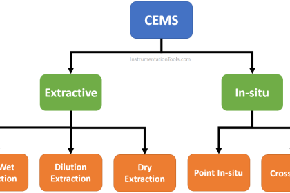
Some analyzers measure the composition of a process stream by directly immersing the sensing element in that stream. This is called in situ measurement, which is a Latin phrase meaning “in the place.” A pH probe inserted into a process pipe, an oxygen probe inserted into the stack of a combustion furnace, and a GFC analyzer measuring the concentration of a gaseous pollutant by shooting a light beam across a process room are all examples of in situ analyzers: the analytical sensing takes place directly within the process environment.
Alternatively, analytical sensing elements may be located some distance away from the process, in which case a representative sample of that process stream must be conveyed to the analyzer for measurement. A great many industrial analyzers function like this, with a system of tubes, heaters, filters, pumps, regulators, and other components working together to provide the remotely located analyzer with a steady stream of process fluid to sample. It should be noted that quite often problems experienced with process analyzers stem from improperly constructed and/or maintained sample systems.
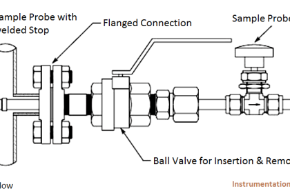
A very simple sample system for a pH analyzer is shown here, the purpose for it being to allow the pH electrode to operate at atmospheric pressure instead of the high pressure inside the process pipe (Note):
Note : In-situ pH probes are manufactured for high-pressure applications, but they suffer short lifespans (due to the accelerated erosion of the measurement glass) and decreased sensitivity (due to the extra thickness of the measurement glass) and are substantially more expensive than pH probes designed for atmospheric pressure conditions.
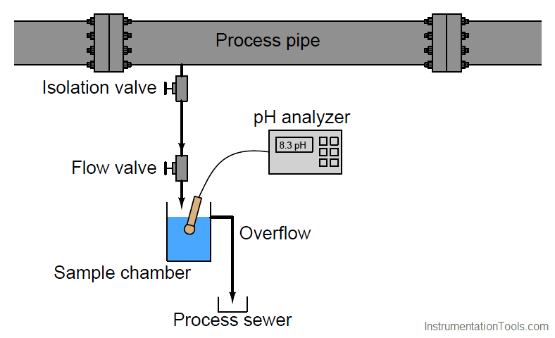
Liquid from the process pipe flows through the isolation and flow-control valves, the rate of flow restricted to a mere trickle, where it continuously fills a sample chamber and overflows into a process sewer designed to transport a constant stream of process liquid. If for some reason a process sewer drain is unsafe, environmentally destructive, or impractical, one may replace the overflow tube with a level control system and pump to re-inject the sample back into the process line. This, of course, adds complexity and expense to the sample system.
Despite the apparent simplicity and necessity of such a sample system, its very existence adds one more layer of fault potential to the measurement system. Imagine, for example, the sample line between the isolation and flow control hand valves becoming plugged with debris from within the process pipe. This would prevent fresh sample from reaching the sample chamber. The pH probe would then measure nothing but old, stale sample liquid rather than a representation of the liquid flowing through the process pipe. The pH analyzer has no way of “knowing” that what it is measuring does not reflect the state of the process, and will report meaningless pH data.
Liquid sample systems may require much more complexity than what is shown here for this simple pH analyzer. To meet the sample needs of some analyzers, we may need to control the flow rate of the sample, the temperature of the sample, and/or filter it for particulates.
Sample systems for gas analyzers tend to be even more complex than sample systems for liquids. Not only is sample pressure control (Note 1 ) , temperature control, and filtering standard for most gas analyzers, the trapping and removal of condensation from gas sample lines is also important, as is the prevention of gas permeation through sample lines. If liquid and/or particulate matter happen to enter a gas analyzer, the results may range from measurement delay to gross measurement error to damage of critical components within the analyzer, depending on the analyzer type and the concentration of inappropriate matter in the sample. Analytical gas samples, as a general rule, must be impeccably clean and dry.
Note 1 : Pressure control is important in gas analysis because changes in sample gas pressure will result in different gas densities, thereby directly affecting how many molecules of the gas of interest will be present and therefore detectable inside the analyzer.
Note 2: Temperature control is important for similar reasons: the gas species of interest may become more reactive as temperature changes, thereby resulting in a stronger indication even when concentration remains constant.
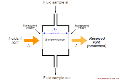
Note 3 : It is important to thoroughly filter the gas input to an analyzer so that contaminants do not foul the sensing element(s). This is rather obvious in the case of optical analyzers, where the light to be analyzed must pass through a transparent window of some kind, and that window must be kept clean of dust, condensation, and any other substances that could interfere with the transmission of light.
Note 4 : Some types of plastic sample tubes are permeable to gases, and so represent potential contamination points when the concentrations of interest are in the range of parts per million (ppm) or parts per billion (ppb). In such critical applications, only metal sample tubes (stainless steel, typically) are appropriate.
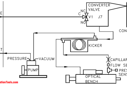
An example of a typical sample system for a set of gas analyzers used to continuously monitor the emissions from the stack of a combustion furnace (CEMS: Continuous Emissions Monitoring System) is shown here:
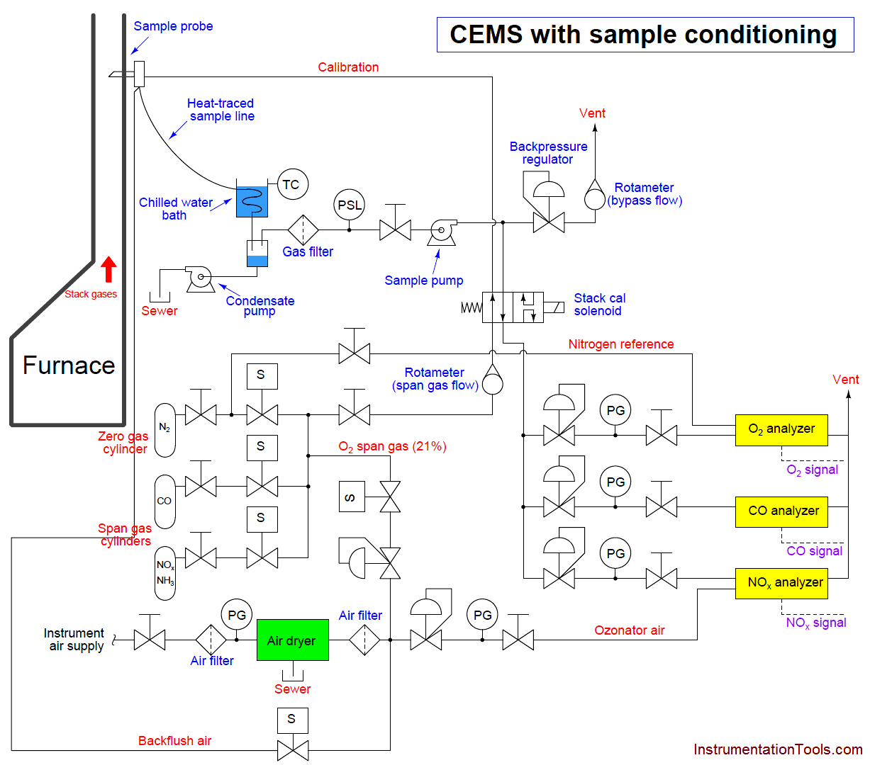
There is much to comment on in this diagram, just focusing on the sample probe and line. Note how the sample probe is beveled so as to avoid picking up any particulate (solid matter) traveling with the furnace exhaust gas. Note also how the sample tube is heat-traced to prevent condensation from gathering in the tube, and how the entire length of the sample line is sloped downhill to prevent any condensed liquid from forming a “trap” that gases would have to bubble through to reach the analyzer system. Once arriving at the analyzer shelter, the sample line immediately plunges into a chilled water bath to force any condensible vapors to condense and be drained away, leaving only a dry gas sample to enter the rest of the analyzer tubing system.
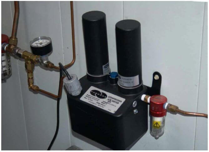
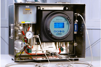
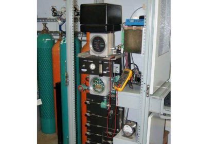
Another feature of this CEMS is an air dryer (shown as a green rectangle), used to remove moisture from compressed air before that air is used within the system. In this particular CEMS, dry air is used both as a span gas for the oxygen analyzer (ambient oxygen concentration being approximately 20.9% by volumetric or molar concentration) as well as feed for the NOx analyzer’s internal ozonator. A photograph of such an air dryer is shown here, part of the CEMS at a gas-fired power plant:
Accurate and reliable operation of any analyzer depends not just on the analyzer itself, but also on all other equipment supporting its role. With analyzer systems such as CEMS, the amount and complexity of supporting equipment is substantial, which means analyzer systems tend to require much more maintenance than other forms of instrumentation. Fault diagnosis is also more complicated for analyzer systems for the same reason.
Turning our attention now to the rest of the sample system, we see it provides the means for automatic calibration of each analyzer, where a computer (most likely a PLC, or a specialized computer sequencing the operation of all three analyzers) periodically shuts off the sample flow to the analyzers and replaces that flow with standard “span gas” to self-check the response of the analyzers. Note how the mixed calibration gas has the option of being injected at the sample probe so as to force the gas mixture to travel down the sample line and through the whole system (with the “stack cal” valve in its default position). While this may seem needless and wasteful, it indeed serves a practical purpose: to test the integrity of the entire system, sample conditioning and all. If, for example, there were some source of contamination entering the sample stream by way of the condensate trap, this would be detected during the self-calibration cycle because the calibration gas mixture would have to pass through the same contaminated area as the normal stack gas sample. Another example is a leak in one of the sample lines, allowing ambient gases to leak in and dilute or otherwise contaminate the sample. A self-calibration system bypassing the whole sample line and conditioning system would not detect the presence of any contamination, and therefore would not be testing the integrity of the whole system.
A photograph of three span gas cylinders used in a CEMS self-calibration system appears here:
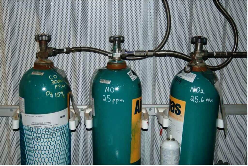
The three span gas mixtures include one with 30 ppm concentration carbon monoxide gas (CO) and 15% concentration oxygen gas (O2), another with nitric oxide gas (NO) at a concentration of 25 ppm, and a third with nitrogen dioxide gas (NO2) at a concentration of 25.6 ppm. The “balance” gas for each of these calibrated mixtures is nitrogen. Each of these span gas mixtures is manufactured at a facility where the concentration quantities are traceable to NIST standards, just like any other calibration-grade measurement standard in instrumentation.
Analytical instruments typically require far more frequent calibration checks than standard instrument types (pressure, level, temperature, flow), and much maintenance labor may be saved by automatic calibration systems. Such routine checks of analyzer calibrations are commonly referred to as drift tests, because their purpose is to verify how far the analyzer’s calibration has “drifted” from its specification. Unfortunately, the very same systems intended to reduce routine maintenance effort also introduce more points for failure, and therefore contribute to the non-routine maintenance needs of the system.


Thanks for this issue, really usefull and well explained. God Bless you for share and teach us.