Instrument Loop Test Requirements
1. Make sure before loop test SAT for related systems shall be completed.
2. Make sure systems peripheral equipment and network system via optical cable link should be ready for function.
3. Make sure the inspection and test report attached in the loop folder as follows:
- Loop test check sheet.
- Instrument engineering index.
- Loop drawing.
- Instrument tubing/piping leakage test report
- Instrument datasheet
- Instrument calibration report
- Cable megger/continuity test report for primary cables and secondary cables.
- Piping and instrumentation drawing.
- Punch list
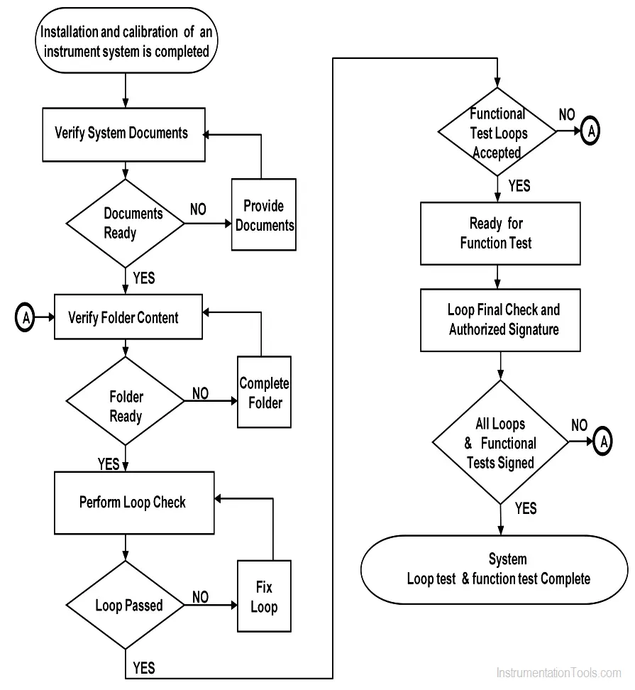
4. Provide a loop test procedure flow chart.
5. Provide typical hook up for analog/digital input/output loop test procedure flow chart.
6. During the loop test, actual pressure shall be applied for the diaphragm sealed/ capillary type transmitter.
7. For temperature loop simulation to be done from the element.
8. The loop temperature error should be in the range of system allowable error.
9. Instrument calibration work shall be completed.
10. Instrument installation and cable termination work shall be completed.
11. The loop test point should be five-points (0, 25%, 50%, 75%, 100%), and in reverse order too.
12. A portable radio transmitter/receiver should be used for the loop test.
13. Each instrument or installation shall be attached a colored label conforming to the following code:
BLUE   -  Pre-installation tested

YELLOW -  Pressure tested

GREEN  -  Cable tested

RED    -  Loop test

WHITE  -  Test fail
14. If the loop test accepted by the client, a loop test sticker can be provided.
Operation and Procedures
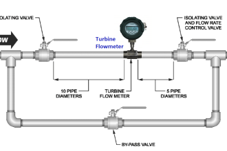
Flow Meter Loop Test
- Check the flow meter, include tag No. and range should correspond with the design datasheet.
- Before connecting the HART communicator, the flow should indicate 0% in DCS.
- Connect the HART communicator, check the tag No., range, and other settings of the flow meter.
- Simulate signal (0%, 25%, 50%, 75%, and 100%) from the field termination by using HART communicator, check the indication in DCS, the alarm set should be check.
- Also, do the above step in reverse order (100% to 0% in steps) and observe the transmitter response.
- Disconnect the HART communicator, check the indication in DCS again. The flow should be 0%.
Level Transmitter Loop Test
- Check the level transmitter, include tag No. and range should correspond with the design datasheet.
- Before connecting the HART communicator, the level should indicate 0% in DCS.
- Connect the HART communicator, check the tag No., range, and other settings of the level transmitter.
- Simulate signal (0%, 25%, 50%, 75%, and 100%) from the field termination by using HART communicator & check the indication in DCS, the alarm set should be checked.
- Also, do the above step in reverse order (100% to 0% in steps) and observe the transmitter response.
- Disconnect the HART communicator & check the indication in DCS again. The level should be 0%.
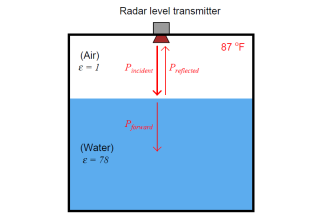
Note: It includes displacement level transmitter, float level transmitter, radar level transmitter, differential pressure transmitter, etc.
Switch Loop Test
- Check the switch, include tag No. and range should correspond with the design datasheet.
- The disconnection of the signal wire and jumper wire will indicate abnormal conditions in DCS.
- Initiate the signal from the site and check the value variation in DCS.
- Disconnect the signal and check the output of DCS.
Note: The above procedure may include a pressure switch, level switch, temperature switch, and flow switch.
Pressure Transmitter Loop Test
- Check the pressure transmitter, include tag No. and range should correspond with the design datasheet.
- Open the drain valve, the pressure output should indicate 0% in DCS, if the pressure transmitter is vacuum type, before connecting the HART communication, the pressure output should be atmospheric pressure.
- Connect the HART communication, check the tag No., range, and other settings of the pressure transmitter.
- Simulate signal (0%, 25%, 50%, 75%, and 100%) from the field termination by using HART communication, check the indication in DCS, the alarm set should be checked, and recorded.
- Also, do the above step in reverse order (100% to 0% in steps) and observe the transmitter response.
- Disconnect the HART communication, check the indication on DCS again.
RTD (without transmitter) Loop Test
- Check the temperature element (RTD) tag no. corresponds with the design datasheet.
- Apply resistance values according to the temperature range from the decade resistance box. Check the corresponding process values in the control room.
Thermocouple (without transmitter) Loop Test
- Check the temperature element (thermocouple) tag no. corresponds with the design datasheet.
- Apply the milli Volts from the process meter according to temperature and check the corresponding process values in the control room.
Temperature Transmitter Loop Test
- Check the temperature transmitter tag No. and range should correspond with the design datasheet.
- Before connecting the HART communication, check the output value of the temperature transmitter in DCS, the temperature value should be the field ambient temperature.
- Connect the HART communication, check the temperature transmitter tag No., range, and set value.
- Simulate signal (0%, 25%, 50%, 75%, and 100%) from field termination by using HART communication, check the indication in DCS, the alarm set should be checked, and recorded.
- Also, do the above step in reverse order (100% to 0% in steps) and observe the transmitter response.
- Disconnect the HART communication, check the indication in DCS again.
Control Valve with Pneumatic Positioner Loop Test
- Check the control valve tag No. and range should correspond with the design datasheet.
- Give the input signal to the control valve (4mA, 8mA, 12mA, 16mA, and 20mA) and check the response of the valve stem position in correspondence with the input signal.
- Also, do the above step in reverse order (20mA, 16mA, 12mA, 8mA, 4mA) and observe the valve response.
- Check the status of the air failure of the control valve.
Vibration Probe Loop Test
- Before starting the loop check, confirm the following calibration/test of the vibration probes.
- All cable termination is completed, vibration probes are properly connected to the proximitor.
- Check the polarity of the wires at the proximitor, (com, -24V, and O/P terminals) connected to the monitor system.
- Confirm monitor are configured for suitable units for axial, radial, and speed measurement.
- Simulate from the TK3 kit for axial, radial vibrations according to the datasheet. (Note the reading on the monitor.)
- Simulate up to the alarm and danger conditions, and confirm the function of the trip relays connected to the shutdown system.
Analyzer Loop Test (with the vendor)
- An analyzer loop shall be ready for checking when the following activities are completed.
- Appropriate calibration/test
- Pneumatic/hydraulic line pressure test.
- All final inspection for analyzer shelter/panel.
- Confirms that analyzer installation and all related items (ex: sampling system) in the loop functions properly. Apply appropriate samples and check for proper reading in the local monitor/panel and in the control room.
Gas Detector Loop Test
- Check the gas detector tag No. and range should correspond with the datasheet.
- Instead of simulating a 4-20mA signal, supply sample test gas to the sensor of the gas detector, and check the output value from DCS.
Loop and Functional Test Work Flow
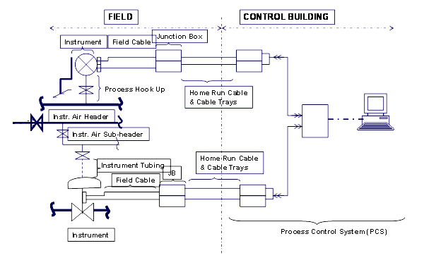
Hook-up for Analog/Digital Loop Test
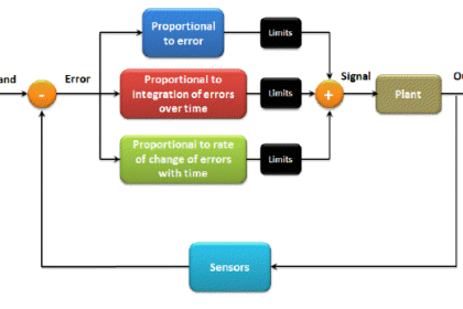
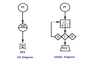
Control Loop
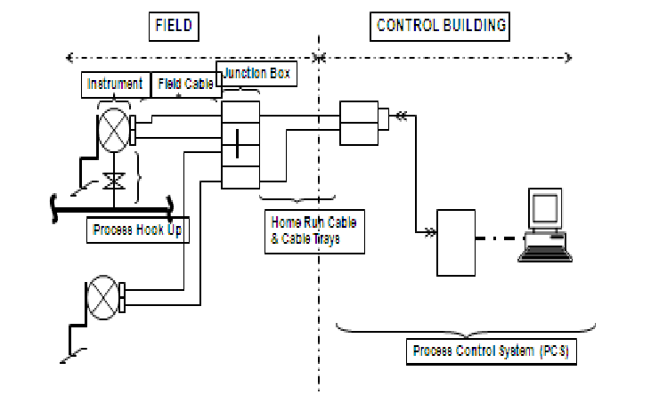
Simple Loop with Local Indication
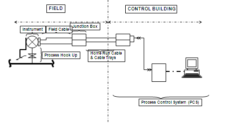
Simple Loop
Author: Mohammed Khaleel
Read Next:
- What is Loop Checking?
- Logic Check Procedure
- Yokogawa DCS System
- Fire Alarm System Commissioning
- Control Valves Pre-Commissioning