Thyristor commutation is a process used in power electronics to Turn OFF a thyristor (also known as a silicon-controlled rectifier or SCR) after it has been turned on.
Once a thyristor is triggered into conduction, it will remain in the conducting state until the current flowing through it drops below a certain level (known as the holding current) or the voltage across it reverses
Types of Commutation
There are mainly two methods of thyristor commutation:
Natural Commutation
In natural commutation, the thyristor turns off by itself when the current through it naturally goes to zero. This occurs in AC circuits when the voltage across the thyristor reverses polarity.
Thyristors are often used in AC applications because they can naturally commutate at every zero-crossing of the AC voltage.
Line Commutation
This is the most common form of natural commutation. The thyristor is turned on when the voltage across it is in the same polarity as the source voltage. It turns off when the source voltage crosses zero, causing the current to naturally drop to zero.
Load Commutation
In some cases, the load itself can provide the means for natural commutation. For instance, inductive loads can cause the current to naturally drop to zero when the thyristor is turned off.
Forced Commutation
Forced commutation is used when it’s necessary to Turn OFF the thyristor before the natural commutation would occur. This is often the case in DC circuits or when precise control over the turn-off time is required.
Forced commutation methods include:
- Class A: Self or Load Commutation
- Class B: Resonant-Pulse Commutation
- Class C: Complementary Commutation
- Class D: Impulse Commutation
- Class E: External Pulse Commutation
Class A Commutation: Self or Load Commutation
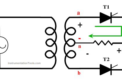
A thyristor’s load commutation is accomplished by connecting the commutating components L and C as shown in Fig. 1. Where R is the load resistance. L and C are connected in series with R when R has a low value.
When R is high, the load is connected across C. These circuits produce the current waveforms depicted on the right side of Fig. when they are powered by DC. It can be seen that current(i) first reaches its greatest value before starting to decline. The thyristor in Fig.1 turns off instantly on its own when the current tends to reverse and decays to zero.
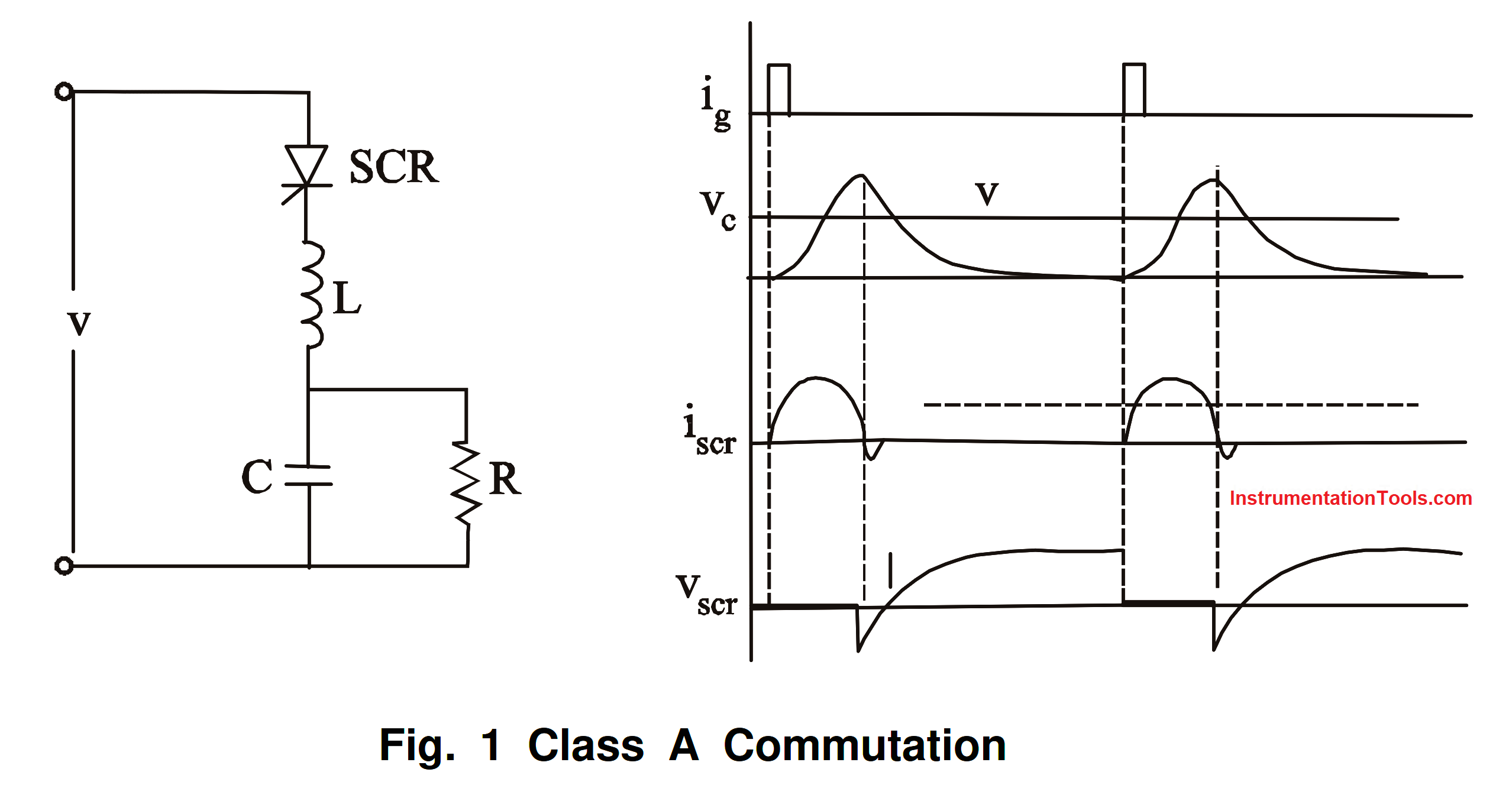
Fig 1 Self or Load Commutation Circuit and Waveform
Anode current flows and charges the C when the SCR is activated. The L-C-R circuit is second-order under-damped. A half cycle is completed by the current flowing through the SCR. The SCR will then attempt to operate in the opposite direction of the inductor current, turning it off. When the SCR turns off, the capacitor voltage reaches its maximum and discharges into the resistance exponentially.
A reverse bias is applied to the SCR until the capacitor voltages revert to the supply voltage V level. The majority of thyristor circuits powered by DC sources commutate under load, or class-A, in a common manner. In order for load commutation to happen in a thyristor circuit, the circuit’s design should be such that when powered by a DC source, the current must naturally have a propensity to decay to zero. DC circuits allow for load commutation, whereas AC circuits do not. The terms resonant commutation and self-commutation are also used to describe class A, or load, commutation.
Class B: Resonant-Pulse Commutation
Before a gate pulse is applied to the SCR, Capacitor C charges to its maximum. Two components make up the current that results from an SCR being activated. R – L load is the conduit through which the constant load current passes. By clamping the load with a freewheeling diode and placing a large reactance in series with it, this is achieved.
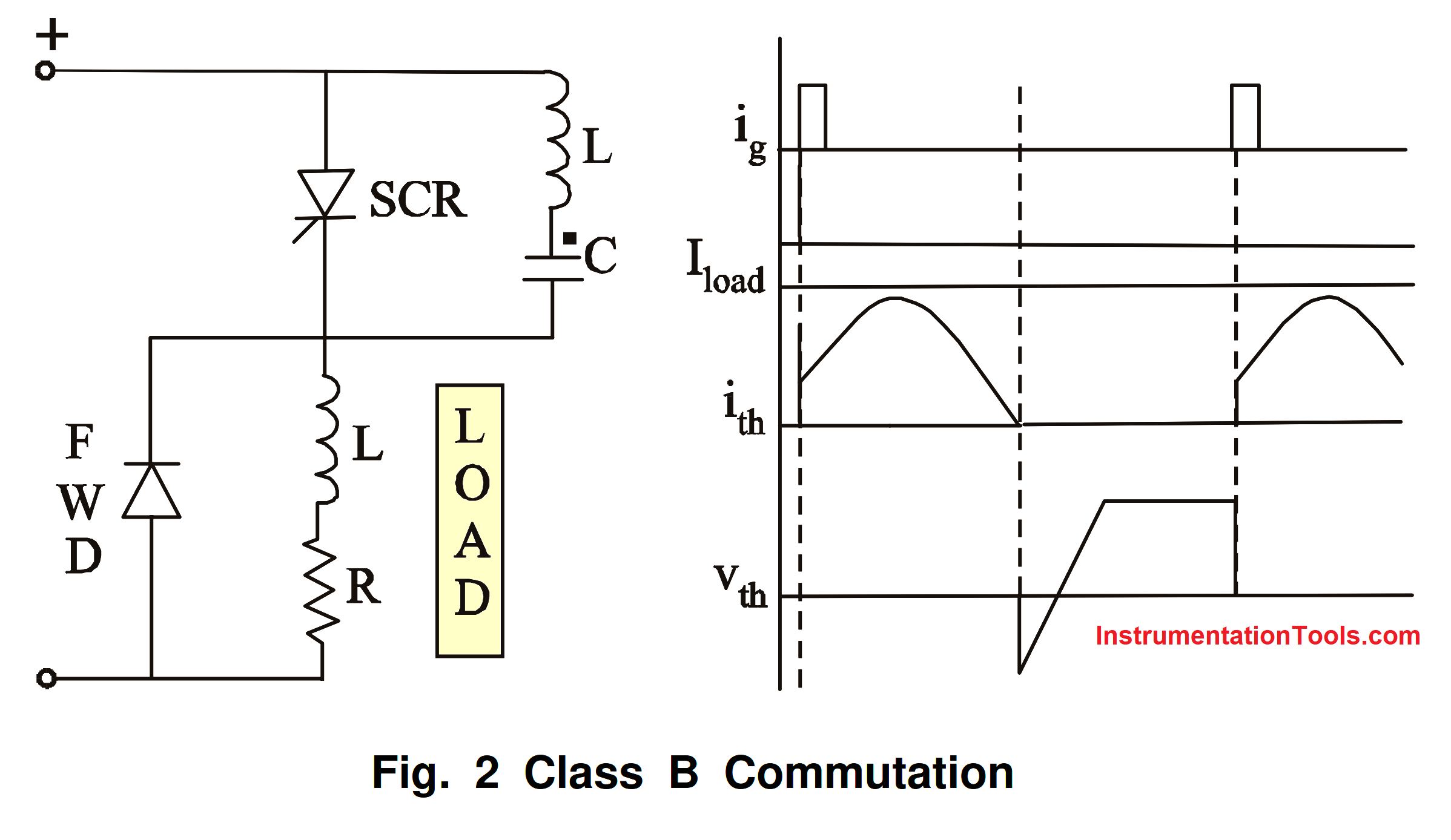
Fig 2 Class B: Resonant-Pulse Commutation circuit and waveform
To charge up C in the opposite direction at the conclusion of the half cycle, a sinusoidal current flows through the resonant L–C circuit. Later, this current will switch directions and flow through the SCR against the load current for a tiny portion of the negative swing until the total current through the SCR is zero.
When the resonant-circuit (reverse) current is just slightly higher than the load current, the SCR will shut off. If the rate of rise of the reapplied voltage is less than the rated voltage and the SCR is still reverse biased for tq > toff, the SCR is shut off.
Class C: Complementary Commutation
Two SCRs are present in this arrangement. One of them might serve as the primary SCR and the other as an auxiliary. Both could be the main SCRs carrying load current. Four SCRs may be used in the design, with the load being connected across a capacitor, and the integrated converter being powered by a current source.
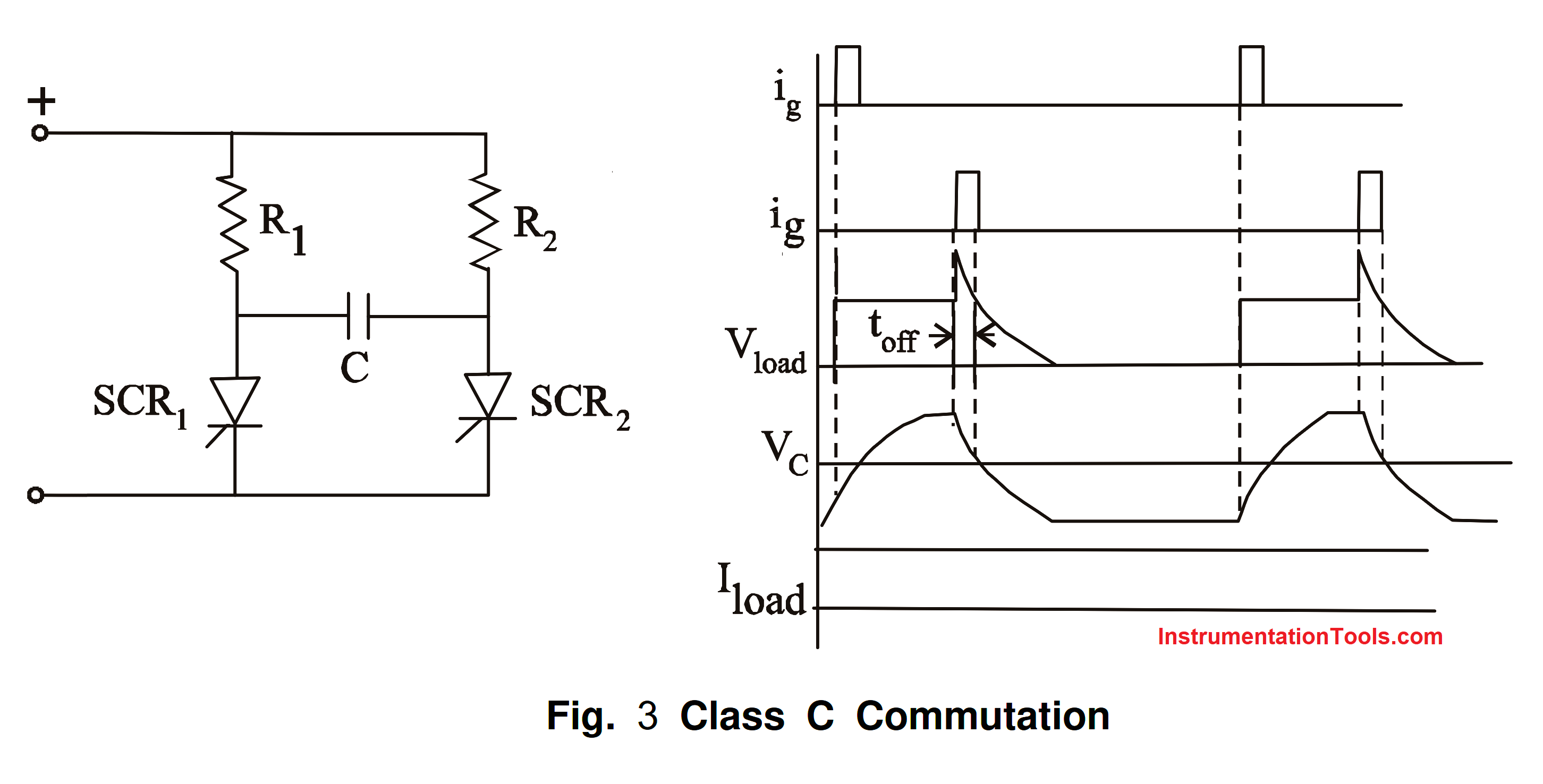
Fig 3 Class C: Complementary Commutation circuit and waveform
Assume SCR2 is active. C then charges in the polarity shown. When SCR1 is activated, C is switched across SCR2 via SCR1, and the discharge current of C opposes the flow of load current in SCR2.
Class D: Impulse Commutation
The Class C can be changed into the Class D in Fig 3. One SCR just carries the load current, with the other serving as an auxiliary to Turn OFF the SCR. The anode lead of the auxiliary SCR would have a resistor, say ten times the load resistance, in it.
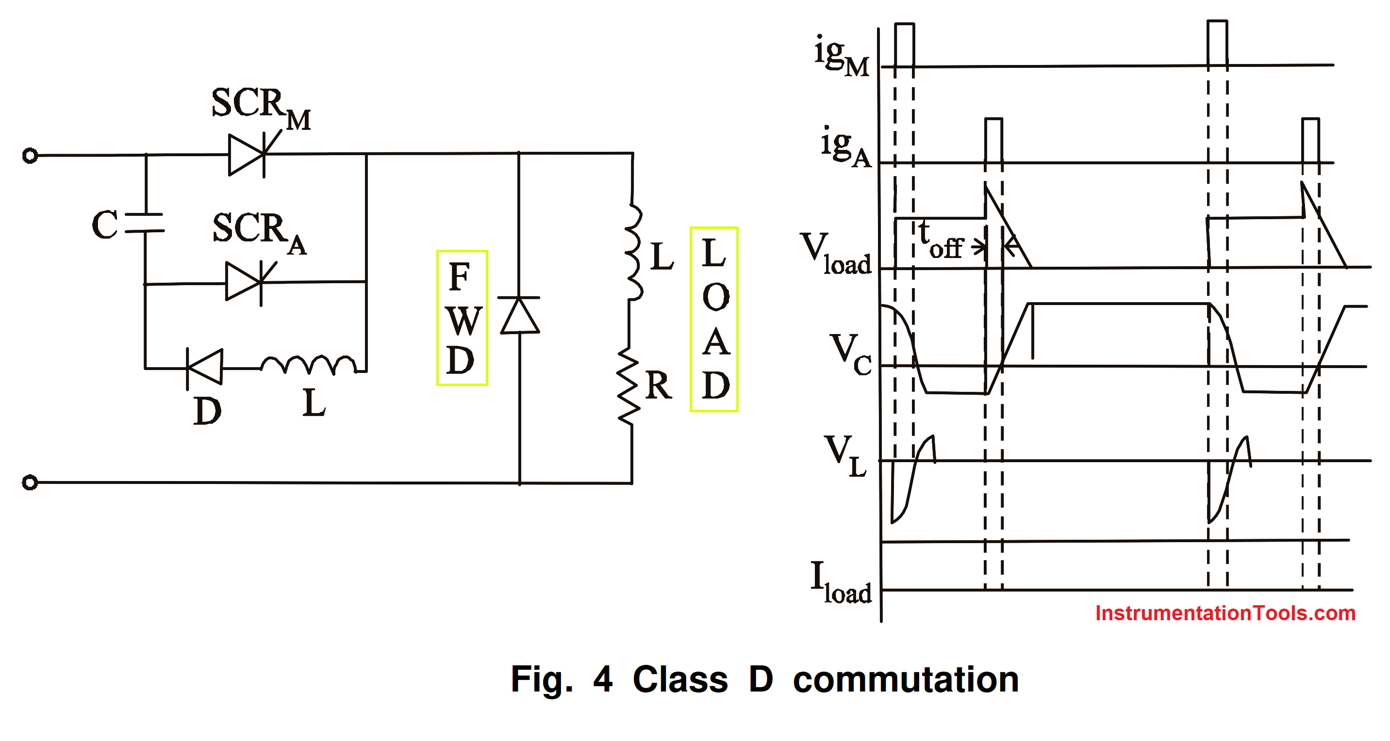
Fig 4 Class D: Impulse Commutation Circuit and Waveform
SCRA will stop operating as soon as C reaches the supply voltage. The capacitor may charge to voltages above the supply voltage if the input lines have a significant amount of inductance. Through the diode-inductor-load circuit, this excess voltage would dissipate.
When SCRM is activated, current travels along two different paths: the load current travels through the load, and the commutating current travels through the C-SCRM-L-D network. The diode D reverses the charge on C and keeps it there.
When SCRA is re-triggered, the voltage across C is sent via SCRA to the SCRM and SCRM is disabled. The capacitor charges again linearly to the dot as positive if the load maintains a constant current as shown in Fig. 4.
Class E: External Pulse Commutation
As a result, the transformer’s pulse reverses the voltage across the SCR, delivers the reverse recovery current, and maintains the voltage negative for the required turn-off duration.
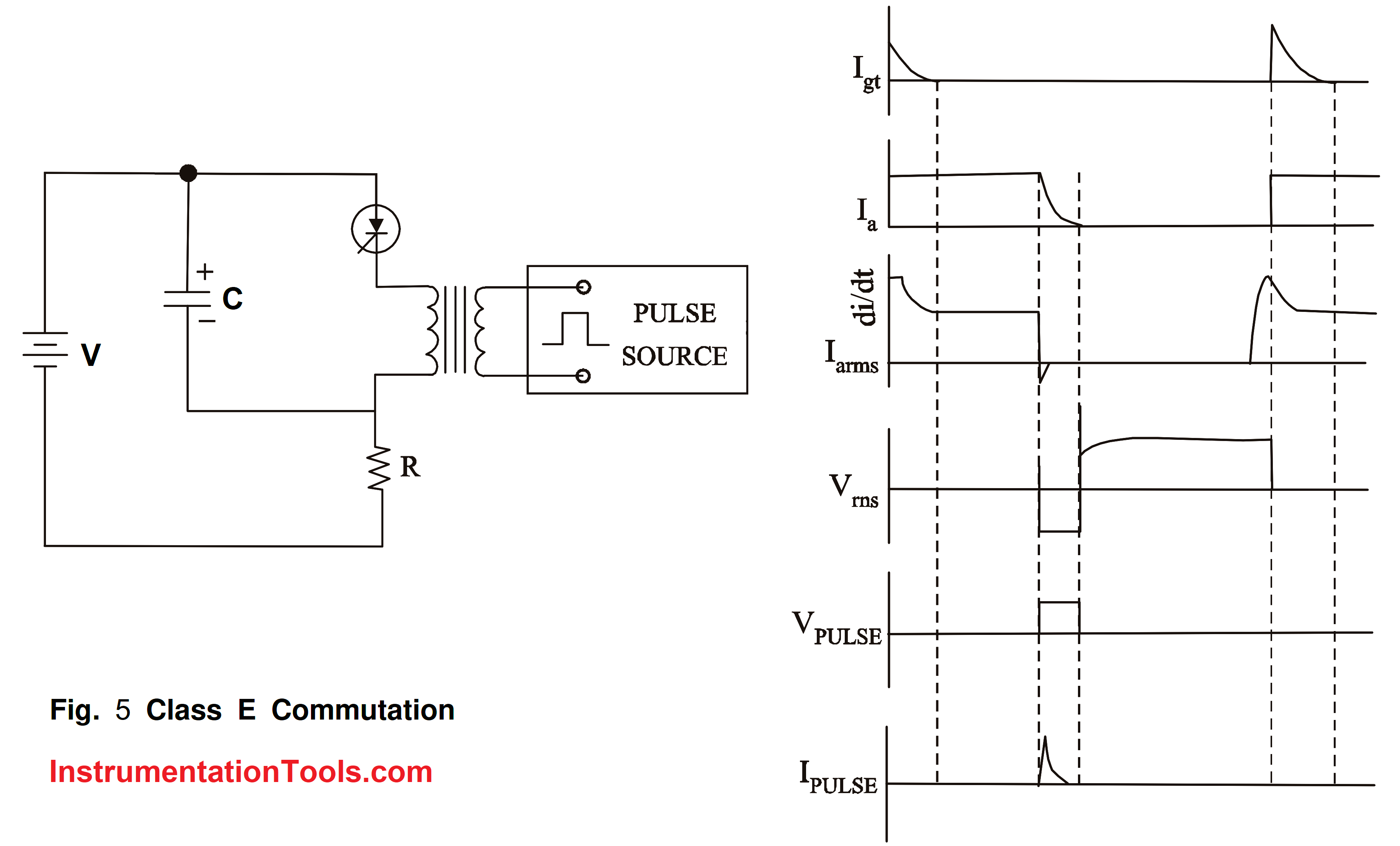
Fig 5 External Pulse Commutation Circuit and Waveform
Thyristor commutation methods are chosen based on the specific requirements of the application. Natural commutation is preferred where possible due to its simplicity and reliability, but forced commutation methods provide more control over the turn-off process when needed.
Reference
- “Power Electronics” P. S. Bimbhra, Khanna Publishers, 2012
- “Power Electronics: Circuits, Devices and Applications”, M H Rashid, Pearson Education
- “Power Electronics”, M-Scheme, K.V. Kandasamy, 2020.
If you liked this article, then please subscribe to our YouTube Channel for Instrumentation, Electrical, PLC, and SCADA video tutorials.
You can also follow us on Facebook and Twitter to receive daily updates.
Read Next:
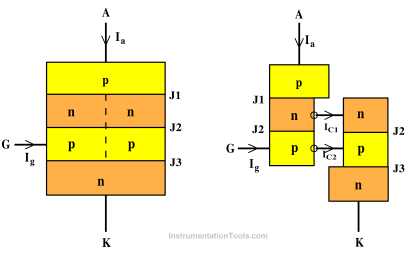
- Thyristor Two Transistor Model
- VI Characteristics of Thyristor
- How to test SCR using a Multimeter
- SCR Triggering Methods Explained
- Types of Power Electronic Devices