Thyristors are semiconductor devices commonly used in power electronics for switching and controlling high-power loads. Thyristor Protection circuits (SCR) are used in power electronics to prevent various faults and overloads to ensure the reliability and longevity of the circuit.
Here are some common thyristor protection circuits and techniques:
Various Types of Protection Circuits
- Overvoltage Protection
- Overcurrent Protection
- Snubber Circuits
- Thermal Protection
- Gate Protection
- Reverse Voltage Protection
- Fuse and Circuit Breaker Protection
- Soft Starting
- Fault Detection and Shutdown
- Ground Fault Protection
Overvoltage Protection
The primary cause of thyristor failure is overvoltage transients. Transient overvoltage causes either circuit malfunction due to an undesired turn-on of a thyristor or permanent device damage due to reverse breakdown.
Internal or external overvoltage can affect a thyristor; the former is caused by the thyristor activity, while the latter is caused by the supply lines or the load circuit.
1. Internal Over voltage
During the commutation of a thyristor, large voltages can be generated inside. When the thyristor anode current is reduced to zero, the anode current reverses due to stored charges.
This reverse recovery current reaches a maximum value, at which point the SCR begins to block. Following this peak, the reverse recovery current decays sharply with significant di/dt.
Due to series inductance L, a significant transient voltage L di/dt is created, the internal overvoltage can be several times the device’s break-over voltage and the thyristor may be irreparably destroyed.
2. External Overvoltage
External overvoltage is generated by interruptions in current flow in an inductive circuit, as well as lightning strikes on the power lines that feed the thyristor systems. Voltage transients are likely to occur when the transformer primary is energized or de-powered when a thyristor converter is fed through a transformer.
Such arise across the load, causing huge fault currents to flow. Overvoltage can also cause thyristor damage by inverse breakdown. Overvoltage must be suppressed using appropriate ways for reliable operation.
3. Suppression of Overvoltage
Thyristors with peak voltage ratings of 2.5 to 3 times their regular peak operating voltage are used to keep the protective components to a minimum. Overvoltage is frequently reduced by employing RC circuits and nonlinear resistors known as voltage clamping devices.
A voltage-clamping (V.C.) device is a non-linear resistor linked across an SCR, as shown in Fig 5. With increasing voltage, the VC device’s resistance fails Fig.1. Under normal working conditions of voltage below the clamping level, the device has a strong resistance and draws only a small leakage curve.
When a voltage surge occurs, the V.C. device runs in the low-resistance area and creates a virtual short circuit across the SCR. As a result of the increased current associated with the virtual short, the voltage drop in the source and line impedances increases, and the voltage across the SCR is clamped to a safe value.
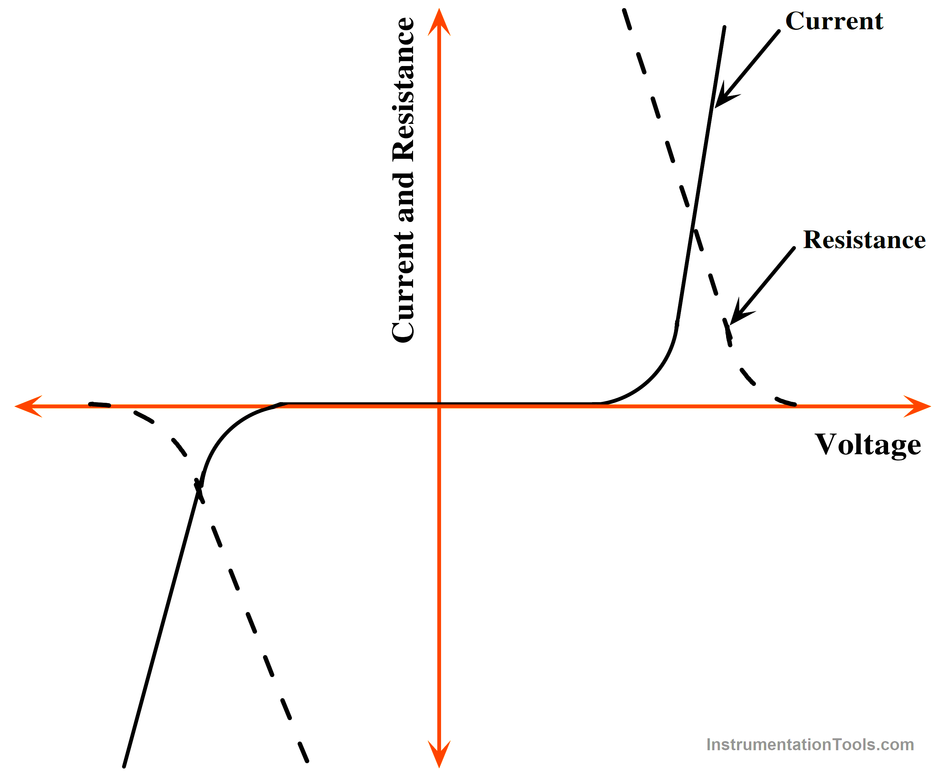
FIG 1. Voltage vs. current and Voltage vs. resistance Characteristics or Voltage Clamping Devices
The operation of the V.C. device returns to its high resistance region when the surge energy is dissipated in the nonlinear resistor. Because thyristors’ voltage clamping ability is lower than that of metal oxide varistors and avalanche-diode suppressors, their application is declining.
As previously indicated, RC snubber is insufficient for SCR overvoltage protection. In fact, thyristors are protected with a combination of RC snubber and V.C. device, as shown in Fig 5.
4. Snubber Circuits
Snubber circuits are used to protect thyristors from voltage transients and dv/dt (rate of voltage change) stress. A snubber typically consists of a resistor and a capacitor connected in parallel to the thyristor. It absorbs and dissipates energy to reduce the rate of voltage rise and prevent false triggering due to voltage transients.
Snubber circuits are required to keep power switches safe and functional. These circuits improve efficiency, increase switching speed, and reduce EMI. A snubber circuit is a power switch protection circuit.
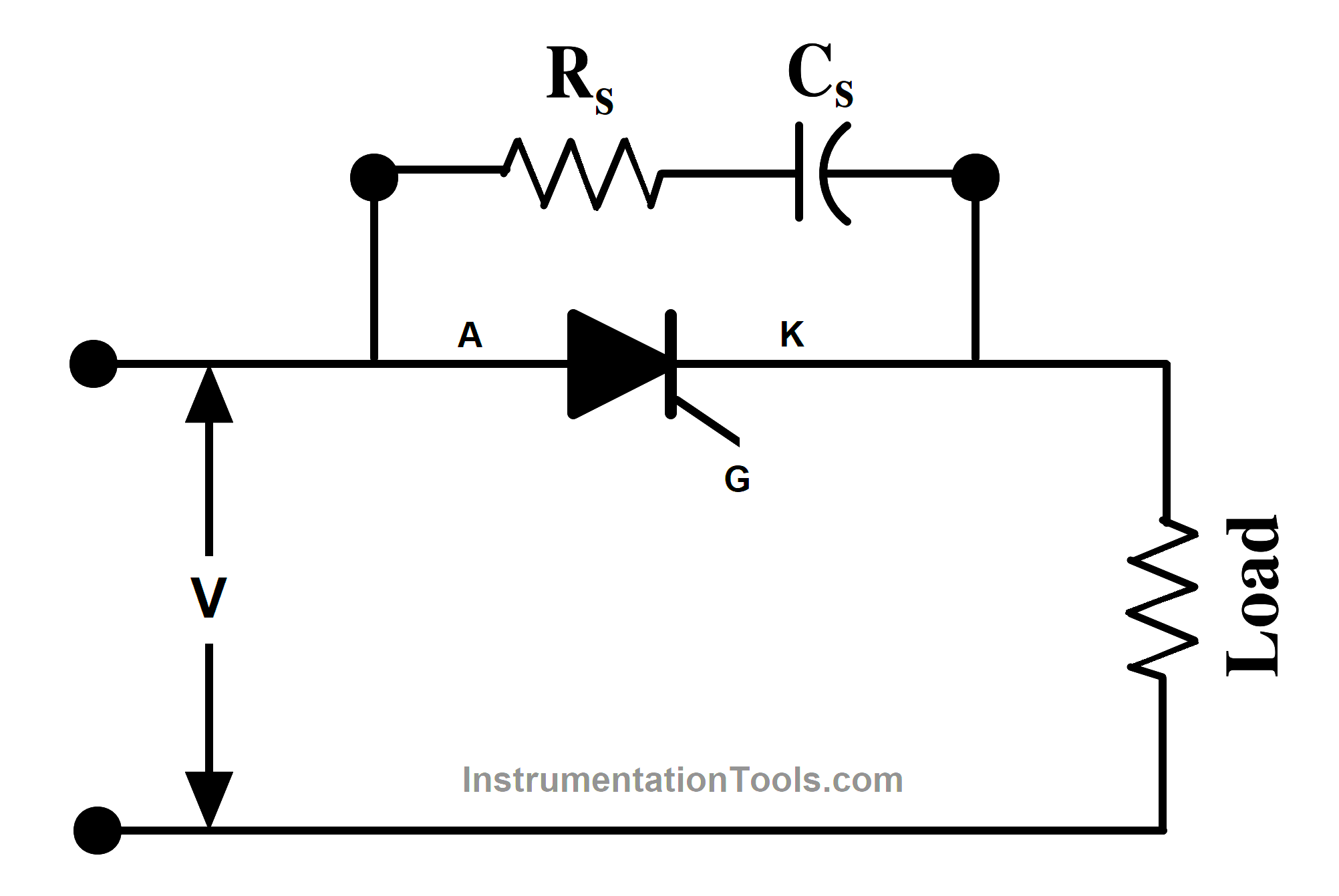
Fig 2. Snubber Circuits
There are various types of snubbers, including RC, diode, and solid-state snubbers, but the RC snubber circuit is the most widely employed. This is true for both rate of climb and damping. This circuit consists of a series resistor and a capacitor linked across a switch shown in Fig. 2. In order to design the Snubber circuits.
The energy dissipated in the snubber resistance is equivalent to the energy held in the capacitors. To lower the peak voltage during turn-off and to light the ring, an RC Snubber put across the switch can be employed. A polarized or non-polarized RC snubber circuit is possible.
Resistors Selection
It is critical that R in the RC snubber has a low self-inductance. Inductance in R raises the peak voltage and tends to defeat the function of the snubber. Low inductance is likewise desirable for R in snubber, but it is not critical because a small amount of inductance increases C’s reset time and reduces the peak current in the switch at turn-on.
The resistor power dissipation must be independent of the resistance R because it dissipates the energy stored in the snubber capacitor during each voltage transition in the capacitor.
Capacitors Selection
Snubber capacitors are subjected to high peak and RMS currents, as well as high dv/dt. The snubber capacitor must meet two conditions. First, the energy stored in the snubber capacitor must be larger than the energy stored in the circuit’s inductance. Second, the time constant of snubber circuits should be small in comparison to the shortest on-time expected, typically 10% of the on-time.
This capacitor is used to reduce dissipation at the switching frequency by allowing the resistor to be effective at the ringing frequency. The optimum design involves matching the capacitor’s impedance to that of the resistor at the ringing frequency.
Overcurrent Protection
Current limiting circuits can be used to protect thyristors from excessive current. Current transformers or shunt resistors can be used to measure the load current. The measurement is compared to a preset threshold, and if the current exceeds this threshold, the thyristor can be turned off or bypassed.
The thermal time constants of thyristors are minimal. As a result, if a thyristor is subjected to overcurrent owing to faults, short circuits, or surge currents, its junction temperature may exceed the rated value, resulting in device damage. As a result, SCR overcurrent protection is required.
The particular type of overcurrent protection utilized is determined by whether the supply system is flexible or rigid. The fault current in a poor supply network is limited by the source impedance being less than the thyristor’s multi-cycle surge current rating. Filter inductance, which is often used in DC and AC drives, may limit the rate of rise of fault current below the thyristor’s multicycle surge current rating.
Overcurrent may be stopped in any of these systems using standard fuses and circuit breakers. However, precise coordination is required to ensure that
- The fault current is terminated before causing damage to the thyristor and
- Only problematic network branches are isolated.
Traditional preventive techniques, however, are insufficient in electrically stiff supply networks. Because the source has minimal impedance, the size, and rate of rise of current are not limited in such systems.
As a result, fault current and junction temperature rise in a matter of milliseconds. In order to preserve thyristors in these stiff supply networks, special fast-acting current-limiting fuses are required.
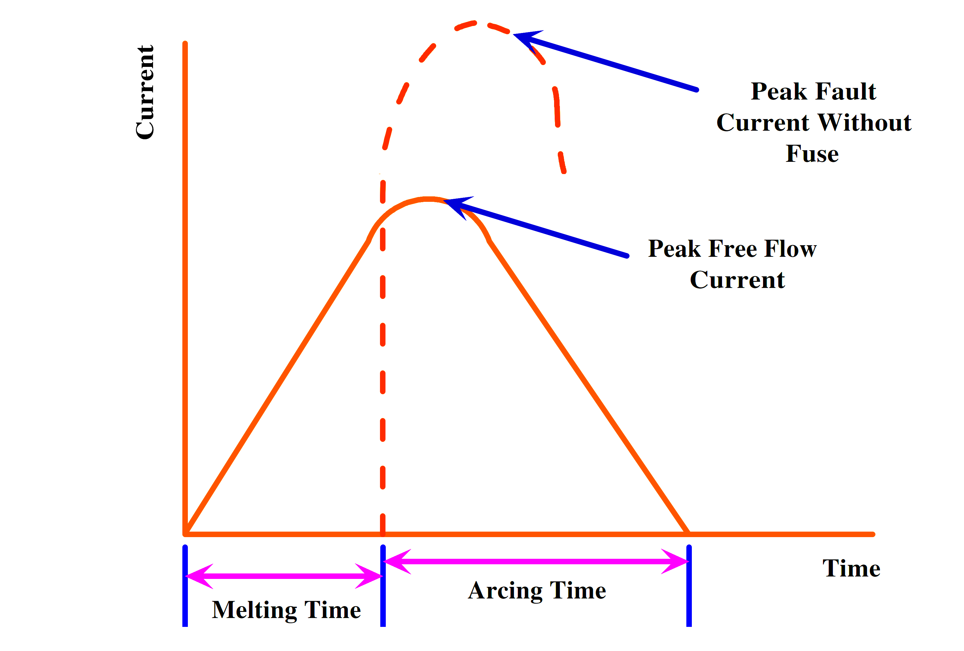
Fig 3. Fuse Limit for Current Rating
A current-limiting fuse is made up of one or more tiny wires that fuse in a very short period of time. The fault is shown in Fig. 3 to occur at the zero crossing of the alternating current sine wave, i.e., at t = 0. The fault current would grow to a certain Peak without a fuse and then follow the dotted curve.
At Peak, a well-chosen current limiting fuse melts. After that, an arc is struck. Depending on the circuit specifications and fuse design, the current continues to climb for a short time after the peak. This current reaches a maximum value, mentioned as the peak free flow point Fig. 3.
Arcing voltage, or recovery voltage, is the voltage across the fuse during the arcing period. This voltage equals the sum of the source voltage and the induced emf in the circuit inductance during the arcing period ta. When the fuse current is abruptly interrupted, the induced e.m.f.
As a result of the high L di/dt, the arcing voltage would be considerable. Arcing voltage should thus be controlled to less than twice the peak supply voltage during fuse design and coordination. If the fuse’s voltage rating is much higher than the circuit voltage, an abrupt current interruption could result in dangerous overvoltage.
Since a circuit breaker has a long tripping period, it is commonly employed to safeguard semiconductor devices from continuous overloads or long-duration surge currents. Thyristors are protected against huge surge currents of extremely short duration by a fast-acting C.L. fuse.
The circuit breaker tripping time and fast-acting fuse fusing time must be correctly coordinated with the thyristor rating. To safely safeguard the thyristor, the fuse’s 12t rating must be lower than that of the SCR.
1. Electronic Crowbar
As the thyristor has a high surge current capability, it can be utilized in an electronic crowbar circuit to protect power converters utilizing SCRs from overcurrent. An electronic crowbar safeguard isolates the power converter quickly before any damage occurs.
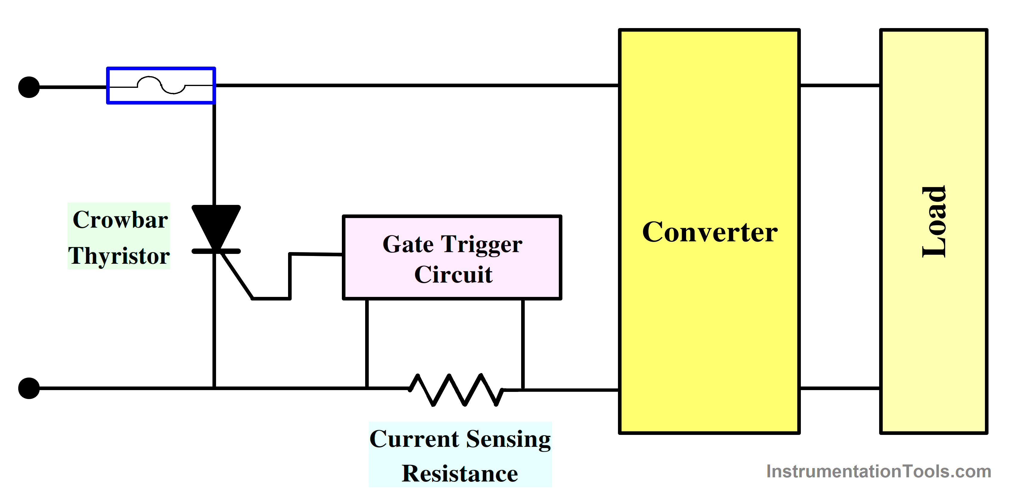
Fig 4. Crow Bar Circuit
The essential principle of electronic crowbar protection is depicted in Fig. 4. The input DC terminals are connected to a crowbar thyristor. The value of the converter current is detected by a current-sensing resistor.
If it exceeds a predetermined threshold, the gate circuit sends a signal to the crowbar SCR, which switches it on in a few microseconds. Crowbar SCR then short-circuits the input terminals, shunting away the converter overcurrent. The crowbar thyristor current is determined by the source voltage and impedance.
Thermal Protection
Thyristors generate heat during operation, and excessive temperature can damage them.
Temperature sensors (thermistors) can be placed near the thyristor to monitor its temperature.
If the temperature exceeds a safe threshold, the thyristor can be turned off to prevent overheating.
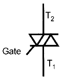
Gate Protection
Protecting the thyristor’s gate is crucial, as gate voltage anomalies can lead to misfiring or damage. Gate protection circuits may include voltage clamping and noise filtering to ensure a stable and safe gate drive.
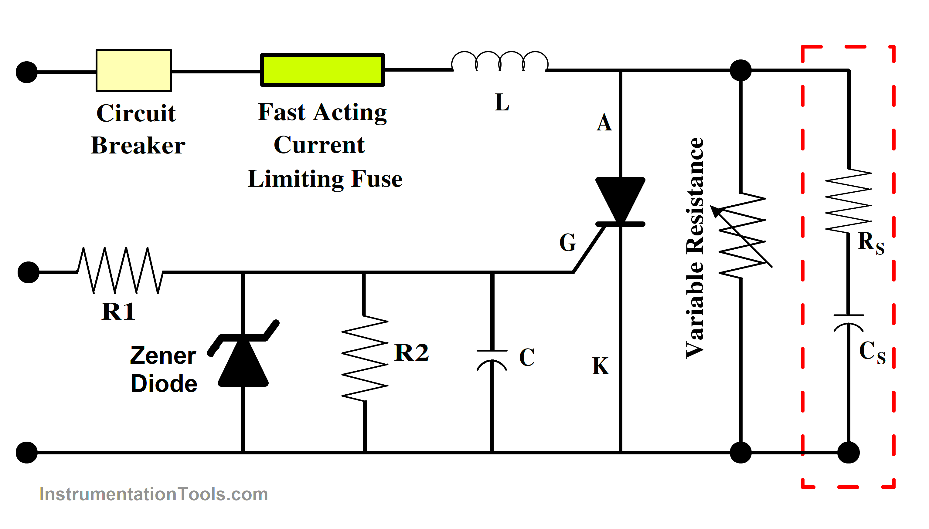
Fig 5. Thyristor Protection Circuit
The presence of spurious, or noisy, firing is a prevalent issue in thyristor circuits. Turning on or off an SCR may cause trigger pulses to be generated in an adjacent SCR. Transients in a power circuit can occasionally Ids-, cause undesired signals to emerge over the gate of a neighboring SCR.
These unwanted trigger pulses may activate the SCR, causing the main SCR to operate incorrectly. Shielded cables or twisted gate leads provide gate protection against such bogus firing. Variable fluxes induced by neighboring transients are not allowed to pass through twisted gate leads or shielded wires.
As a result, no e.m.f. is induced in these cables, reducing spurious thyristor firing. To bypass noise signals, a capacitor and a resistor are connected across the gate to the cathode, as shown in Fig. 5. The capacitor must be smaller than 0.1F and must not degrade the gate pulse’s waveform.
Reverse Voltage Protection
Thyristors are sensitive to reverse voltage. A reverse diode is often connected in parallel with the thyristor to prevent reverse voltage from damaging it.
Fuse and Circuit Breaker Protection
External fuses or circuit breakers can be added to protect the thyristor and the circuit from short circuits and overloads. These devices should be selected to match the rated current and voltage of the thyristor.
Soft Starting
Soft-start circuits gradually increase the voltage or current supplied to the thyristor, reducing the stress on the device during startup.
Fault Detection and Shutdown
Monitoring circuits can continuously check for faults such as short circuits or open circuits.
If a fault is detected, the thyristor can be quickly turned off to prevent further damage.
Ground Fault Protection
Ground fault detection circuits can protect against ground faults in the load circuit, which could otherwise damage the thyristor.
The specific protection circuit used depends on the application and the thyristor’s rating. It’s essential to design protection circuits carefully to ensure the safe and reliable operation of thyristor-based systems.
Additionally, proper circuit layout and cooling systems should be considered to manage heat dissipation and maintain safe operating temperatures.
Reference
- “Power Electronics” P. S. Bimbhra, Khanna Publishers, 2012
- “Power Electronics: Circuits, Devices and Applications”, M H Rashid, Pearson Education
- “Power Electronics”, M-Scheme, K.V. Kandasamy, 2020.
If you liked this article, then please subscribe to our YouTube Channel for Instrumentation, Electrical, PLC, and SCADA video tutorials.
You can also follow us on Facebook and Twitter to receive daily updates.
Read Next:
- Thyristors Turn ON Methods
- Thyristor History, Types, Principle
- IGBT Characteristics & Advantages
- Power Electronic Devices Specifications
- Power Diode Characteristics & Advantages