Inst ToolsInst ToolsInst Tools
  • Courses
  • Videos
  • Q & A
    • Interview
      • Instrumentation
      • Electronics
      • Electrical
      • Practical Questions
    • MCQ
      • Instrumentation MCQ
      • Electrical MCQ
      • Electronics MCQ
      • Control Systems MCQ
      • Analog Electronics MCQ
      • Digital Electronics MCQ
      • Power Electronics MCQ
      • Microprocessor MCQ
      • Multiple Choice Questions
  • EE
    • Electronics
      • Electronics Q & A
      • Electronic Basics
      • Electronic Devices & Circuits
      • Electronics Animation
      • Digital Electronics
    • Electrical
      • Electrical Basics
      • Electrical Q & A
      • Power Electronics
      • Electrical Machines
      • Electrical Animation
      • Power Systems
      • Switchgear & Protection
      • Transmission & Distribution
  • Measure
    • Control Valves
    • Calibration
    • Temperature
    • Pressure
    • Flow
    • Level
    • Analyzers
    • Switches
    • Vibration
    • Solenoid Valve
  • Control
    • PLC Tutorials
    • Control Systems
    • Safety Instrumented System (SIS)
    • Communication
    • Fire & Gas System
  • More
    • Design
    • Tools
    • Animation
    • Basics
    • Formulas
    • Standards
    • TextBooks
    • Common
    • Software
    • Excel Tools
    • Erection & Commissioning
    • Process Fundamentals
    • Videos
    • Books
Search
All rights reserved. Reproduction in whole or in part without written permission is prohibited.
Reading: R R-C Firing Circuits Disadvantages
Share
Notification Show More
Font ResizerAa
Inst ToolsInst Tools
Font ResizerAa
  • Courses
  • PLC Tutorials
  • Control Systems
Search
  • Courses
  • Videos
  • Q & A
    • Interview
    • MCQ
  • EE
    • Electronics
    • Electrical
  • Measure
    • Control Valves
    • Calibration
    • Temperature
    • Pressure
    • Flow
    • Level
    • Analyzers
    • Switches
    • Vibration
    • Solenoid Valve
  • Control
    • PLC Tutorials
    • Control Systems
    • Safety Instrumented System (SIS)
    • Communication
    • Fire & Gas System
  • More
    • Design
    • Tools
    • Animation
    • Basics
    • Formulas
    • Standards
    • TextBooks
    • Common
    • Software
    • Excel Tools
    • Erection & Commissioning
    • Process Fundamentals
    • Videos
    • Books
Follow US
All rights reserved. Reproduction in whole or in part without written permission is prohibited.
Inst Tools > Blog > Power Electronics > R R-C Firing Circuits Disadvantages

R R-C Firing Circuits Disadvantages

Last updated: September 19, 2016 3:58 am
Editorial Staff
Power Electronics
No Comments
Share
2 Min Read
SHARE

Firing Circuits:

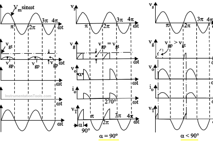
Gate triggering is the most commonly used turn-on method employed to switch on the thyristors. Triggering circuits is also called firing circuits. There are various firing circuits available. R-Firing circuits is simple but suffer from limited firing circuits. Firing angle is limited between 0o to 90o.

In actual practice firing angle can be varied between 3o to 90o. Limitation of the firing angle range of R-Firing circuit is eliminated by introducing a capacitor and a diode. Thus R-C firing circuits can increase the firing angle limitation range. Theoretically firing angle can be varied from 0o to 180o. However due to low voltage at 0o and 180o thyristor cannot be turn-on. Hence practically the range of firing angle is between 3o and 177o.

Both R and R-C firing circuits suffer from following disadvantage:

  • They can be employed in power circuits having only one thyristor
  • They are capable of open loop control only
  • Due to lower voltages near 0o to 180o, gate current is small. Especially in R-C firing circuit, near 180o gate current is minimum due to maximum value of R. This will increase the turn on time, especially for R-L load, leading to higher turn on loss
  • Higher frequency gate signal is desirable for reliable turn on. Both the circuits are not capable of providing the same
  • There is no electrical isolation between control circuit and power circuit

However the circuits are simple and cheap. R-C firing circuits is widely used in low power thyristor controllers, such as solid state ac regulators for speed control of fans and blowers. R-C firing circuits can also acts as snubber circuits

Don't Miss Our Updates
Be the first to get exclusive content straight to your email.
We promise not to spam you. You can unsubscribe at any time.
Invalid email address
You've successfully subscribed !

Continue Reading

Types of IGBT
Power Transistor – Structure, Biasing, Characteristics, Advantages
Thyristor Commutation Techniques – Types, Working Principles
Power Electronics – Full-wave Rectifier With R and RL Load
How Snubber Circuit works ?
Thyristors – Switching, Two Transistor Model, Advantage, Applications
Share This Article
Facebook Whatsapp Whatsapp LinkedIn Copy Link
Share
Leave a Comment

Leave a Reply Cancel reply

Your email address will not be published. Required fields are marked *

Stay Connected

128.3kFollowersLike
69.1kFollowersFollow
208kSubscribersSubscribe
38kFollowersFollow

Categories

Explore More

Crowbar fault protection circuit
IGBT – Symbol, Construction, Working, Characteristics, Advantages
Introduction to Thyristor – History, Types, Principle, Advantages
SCR Switching Characteristics
Power Diode – Characteristics, Construction, Working, Advantages
Thyristor Protection Circuits (SCR) – Types, Principle, Explanation
Phase Controlled Rectifier – Half Controlled Rectifier with R Load
MCT (MOS Controlled Thyristor) – Symbol, Working, Characteristics, Advantages

Keep Learning

triac

Turning Off SCR – Commutation

Types of Power Electronic Devices

Power Electronic Devices Specification and Classification

Resistance firing of an SCR in a half-wave circuit

Thyristor Triggering Circuits – Types, Explanation, Waveforms (SCR)

Power Electronics Objective Questions

Power Electronics Objective Questions

RC Triggering

SCR Triggering Methods

Single Phase Half-controlled Rectifier RL Load With FD

Phase-Controlled Half-Wave Rectifier With Freewheeling Diode

How to test SCR using Multimeter

How to test SCR using Multimeter

Procedure to test the TRIAC

How to Test TRIAC with Multimeter

Learn More

How to Locate Faults in Cables? - Fault Analysis and Location

How to Locate Faults in Cables? – Fault Analysis & Location

Power Electronics Objective Questions

Types of Diodes Objective Questions

Instrumentation Engineering Root Cause Analysis

Instrumentation Engineering Problems Solved – Root Cause Analysis

LCS Configuration equipped with LOTO Facility

Motor Control Signal Interface

What is Star Topology

Network Topologies Selection Factors and Comparison

Siemens S7-200 PLC

Programmable Logic Controller (PLC) Questions and Answers – 13

Digital Electronics Objective Questions

Digital Electronics Objective Questions – Set 4

Range Finders

Range Finders – Ultrasonic, Light, & Global Positioning Systems

Follow US
All rights reserved. Reproduction in whole or in part without written permission is prohibited.
Welcome Back!

Sign in to your account

Username or Email Address
Password

Lost your password?