Inst ToolsInst ToolsInst Tools
  • Courses
  • Automation
    • PLC
    • Control System
    • Safety System
    • Communication
    • Fire & Gas System
  • Instrumentation
    • Design
    • Pressure
    • Temperature
    • Flow
    • Level
    • Vibration
    • Analyzer
    • Control Valve
    • Switch
    • Calibration
    • Erection & Commissioning
  • Interview
    • Instrumentation
    • Electrical
    • Electronics
    • Practical
  • Q&A
    • Instrumentation
    • Control System
    • Electrical
    • Electronics
    • Analog Electronics
    • Digital Electronics
    • Power Electronics
    • Microprocessor
  • Request
Search
  • Books
  • Software
  • Projects
  • Process
  • Tools
  • Basics
  • Formula
  • Power Plant
  • Root Cause Analysis
  • Electrical Basics
  • Animation
  • Standards
  • 4-20 mA Course
  • Siemens PLC Course
Reading: Starting of DC Motors
Share
Font ResizerAa
Inst ToolsInst Tools
Font ResizerAa
  • Courses
  • Design
  • PLC
  • Interview
  • Control System
Search
  • Courses
  • Automation
    • PLC
    • Control System
    • Safety System
    • Communication
    • Fire & Gas System
  • Instrumentation
    • Design
    • Pressure
    • Temperature
    • Flow
    • Level
    • Vibration
    • Analyzer
    • Control Valve
    • Switch
    • Calibration
    • Erection & Commissioning
  • Interview
    • Instrumentation
    • Electrical
    • Electronics
    • Practical
  • Q&A
    • Instrumentation
    • Control System
    • Electrical
    • Electronics
    • Analog Electronics
    • Digital Electronics
    • Power Electronics
    • Microprocessor
  • Request
Follow US
All rights reserved. Reproduction in whole or in part without written permission is prohibited.
Inst Tools > Blog > Electrical Theory > Starting of DC Motors

Starting of DC Motors

Last updated: July 29, 2018 12:46 pm
Editorial Staff
Electrical Theory
No Comments
Share
4 Min Read
SHARE

At the moment a DC motor is started the armature is stationary and there is no counter EMF being generated. The only component to limit starting current is the armature resistance, which, in most DC motors is a very low value (approximately one ohm or less), as shown in below Equation.

Generator Action in a Motor Formula

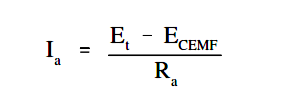
In order to reduce this very high starting current, an external resistance must be placed in series with the armature during the starting period. To show why this is essential, let us consider a 10-hp motor with an armature resistance of 0.4 ohms. If the motor were supplied by a 260 VDC source, the resulting current would be as shown in Equation.

Generator Action in a Motor Formula

Ia =  ( 260 – 0 ) / 0.4  =  650 amps

This large current is approximately twelve times greater than actual full-load current for this motor. This high current would, in all probability, cause severe damage to the brushes, commutator, or windings. Starting resistors are usually incorporated into the motor design to limit starting current to 125 to 200 percent of full load current.

The amount of starting resistance necessary to limit starting current to a more desirable value is calculated using Equation.
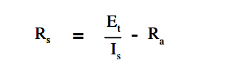
Starting of DC Motors

where

Rs = starting resistance
Et = terminal voltage
Is = desired armature starting current
Ra = armature resistance

Example:

If the full load current of the motor mentioned previously is 50 amps, and it is desired to limit starting current to 125% of this value, find the required resistance that must be added in series with the armature.

Starting of DC Motors

Rs =  { 260 / (125 x 50) } – 0.4

Rs = 3.76 Ω

The starting resistors are used in a DC motor by placing them in the starting circuit of the motor controller that is used to start the DC motor. Starting resistors are normally of variable resistances, with the value of resistance in the circuit at any time being either manually or automatically controlled.

The maximum amount of resistance will always be inserted when the motor is first started. As the speed of the motor increases, counter EMF will begin to increase, decreasing armature current. The starting resistors may then be cut out, in successive steps, until the motor reaches full running speed.

DC Motor Ratings

The nameplate ratings of a DC motor refer to the conditions of voltage, current, speed, and power at which the motor is normally operated. The principal rating is known as the continuous rating, which is the rating described on the nameplate of a motor. The continuous power rating is a thermal rating. At this power, the motor can be operated for long periods of time without a large rise in temperature and beyond the limits of the conductor insulating material, bearings and other components, which are greatly affected by temperature.

The speed rating of a DC motor is often given on the nameplate. This speed is the upper limit at which a motor can be operated without mechanical damage occurring.

Don't Miss Our Updates
Be the first to get exclusive content straight to your email.
We promise not to spam you. You can unsubscribe at any time.
Invalid email address
You've successfully subscribed !

Continue Reading

Electric Circuit : Open & Short Circuits
Single Phase Power Wiring Schemes
Inductive Time Constant
Three Phase Systems
Capacitance
DC Circuit Analysis Node Equations
Share This Article
Facebook Whatsapp Whatsapp LinkedIn Copy Link
Share
Leave a Comment

Leave a Reply Cancel reply

Your email address will not be published. Required fields are marked *

Stay Connected

128.3kFollowersLike
69.1kFollowersFollow
210kSubscribersSubscribe
38kFollowersFollow

Categories

Explore More

Capacitor
Transformer Theory of Operation
Battery Operation : Series and Parallel
Ground Detector Principle
Classification of Transformers
AC Generator Voltage Regulators
Circuit Breaker Control Circuit
Electrical System Components and Protection Devices

Keep Learning

Electrical Wiring Terminology

Electrical Wiring Terminology

Compounded DC Generator

Compound Generators

Current Law

Applying Kirchhoff’s Current Law

Types of Batteries

Types of Batteries

Calculate Power in Series RC Circuit

Calculate Power in Series RC Circuit

Battery Interview QuBattery Interview Question and Answersestion and Answers

Battery Terminology

Calculate Power in Parallel RL Circuit

Calculate Power in Parallel RL Circuit

Transformer Efficiency

Transformer Efficiency

Learn More

What is calibration?

Semiconductor Fuse

What is a Semiconductor Fuse?

Lead Acid Battery Operation

How does a Lead Acid Battery Work?

Calculate-current-4-20ma-from-process-varibale-pv

Calculate Current (4-20ma) from Process variable PV

Selection of Weighing Balance

Selection of Weighing Balance and Weight for Calibration

Sequential Timer Control of Lamps

Schneider PLC Example: Control Lamps Sequences

Hydraulic Actuator

Types of Valve Actuators

Lightning Arrester Bursts Problem

Frequent Feeder-A Lightning Arrester (LA) Bursts – Root Cause Analysis

Menu

  • About
  • Privacy Policy
  • Copyright

Quick Links

  • Learn PLC
  • Helping Hand
  • Part Time Job

YouTube Subscribe

Follow US
All rights reserved. Reproduction in whole or in part without written permission is prohibited.
Welcome Back!

Sign in to your account

Username or Email Address
Password

Lost your password?