Crowbar circuit is used to protect circuit or equipment under fault condition
Over Current Causes:
- Over current flow through thyristors in a circuit due to:
- Flow of short circuit current on the load
- Simultaneous triggering two thyristors in series in a circuit
- Sustained over load
- Stalling of an electrical motor
A Conventional fuse will take quite some time to clear the fault an is not suitable for protection of the device. Fast acting semiconductor fuses are connected in series with each thyristor.
Crowbar Circuit:
A Crowbar circuit is used to protect circuit or equipment under the fault condition. It consists of thyristor of a rating well in higher than the rating of the devices that are to be protected. On detection of the fault, crowbar thyristor is fired consequently fuse blows. Thus the devices are protected against over current. Crowbar protection is recommended for MOSFET circuits.
A crowbar circuit is a method of protecting a circuit against high voltages (overvoltage) in the event of a power supply malfunction or power surge. This is especially useful in a device using TTL components as these are very sensitive to overvoltage. However, there are many other devices which can be damaged by overvoltage.
A crowbar circuit works by sensing a voltage that is above a certain threshold and shorting out the power supply. This causes a voltage drop in the rest of the circuit and current surge through the power supply that will trip a circuit-breaker or blow a fuse. The circuit must have a fuse or circuit-breaker, as without it the power supply or the crowbar circuit will be damaged. Crowbar circuits are so named because their activation is similar in effect to dropping a crowbar across bus bars (heavy duty power supply lines).
A typical crowbar circuit is as follows:
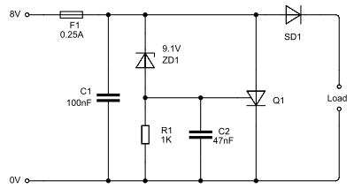
This crowbar circuit has an power supply, and triggers at 9.1V. To change the power supply rating, the zener diode, ZD1, needs to be changed to reflect the new trigger voltage. It should be about 1V higher than the nominal supply voltage.
- Fuse F1 is the fuse that blows if the current drawn by the circuit exceeds 250mA. This can be increased as needed, but make sure the thyristor Q1 has a higher current rating than the fuse. Typically this fuse is a resettable fuse.
- Capacitor C1’s purpose is to reduce small, harmless, voltage spikes or noise which may trigger the circuit.
- ZD1 is the Zener diode which detects the overvoltage condition. At the trigger voltage (here 9.1V), its resisitance decreases suddenly, bringing the junction with R1 and the gate of Q1 high.
- R1 is a pull-down resistor which holds the gate of thyristor Q1 low when ZD1 is not triggered. Its other function is to provide a voltage difference for capacitor C2 to “snub” Q1 with. Without this, the capacitor would be shorted out and useless.
- C2 is a snubber capacitor to prevent the thyristor being triggered by accident on being powered up. It must have a value high enough to snub Q1, but low enough so that the residual charge does not cause a transient “high” state at the gate of Q1 when powered up.
- Q1 is the thyristor which is turned on by ZD1’s breakdown. This provides a short-circuit between the power rails, blowing the fuse.
- SD1 is a Schottky diode to prevent capacitances in the main circuit triggering the crowbar circuit. Normal diodes can be used, but they have a larger voltage drop than Schottky diodes.


