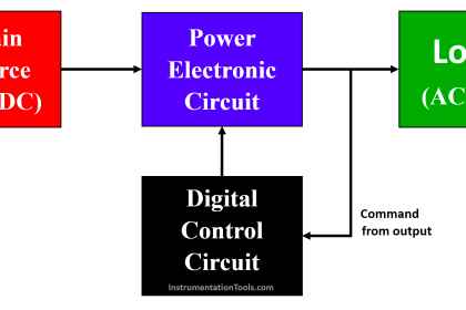
A phase-controlled rectifier is an electronic circuit that converts alternating current (AC) to direct current (DC) using controlled semiconductor devices, such as thyristors or silicon-controlled rectifiers (SCRs).
Unlike uncontrolled rectifiers, which conduct throughout the entire AC cycle, phase-controlled rectifiers allow the conduction angle (the portion of the AC cycle during which the rectifier conducts) to be controlled. This provides a way to regulate the output voltage and current.
In a phase-controlled rectifier circuit, the firing angle (also known as the delay angle or conduction angle) determines the portion of the input AC waveform that is rectified and converted to DC.
Controlling the firing angle, the output voltage and current can be adjusted, therefore it is possible to control the power delivered to the load.
Phase-controlled rectifiers are widely used in various applications, including motor drives, power supplies, and voltage regulators.
Phase Controlled Rectifiers
Here we show the types of phase-controlled rectifiers.

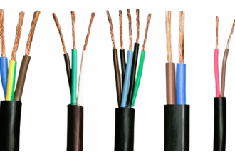
Fig.1. Various Types of Phase-Controlled Rectifiers
There are three main types of phase-controlled rectifiers:
- Half-Wave Rectifier: In a half-wave rectifier, only one half (either positive or negative) of the input AC waveform is rectified.
- Full-Wave Rectifier: In a full-wave rectifier, both halves of the input AC waveform are rectified, resulting in a smoother DC output compared to a half-wave rectifier.
- Full-Wave Bridge Rectifier: This is a type of full-wave rectifier configuration that uses a bridge of diodes or SCRs to rectify both halves of the AC waveform. It is the most common type of phase-controlled rectifier due to its efficiency and ability to produce a constant DC output.
Phase-controlled rectifiers are fundamental components in power electronics and are essential for various applications where controlled DC power is required from an AC power source.
Half Controlled Rectifier
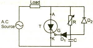
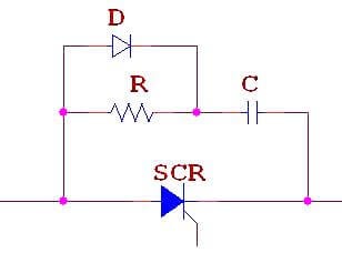
A half-controlled rectifier is a type of phase-controlled rectifier circuit where only one of the rectifying diodes is replaced with a controllable semiconductor device, usually a thyristor or silicon-controlled rectifier (SCR).

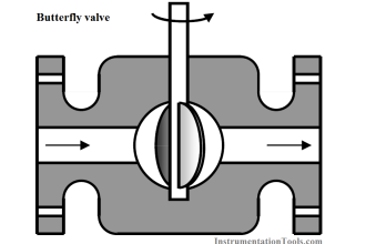
Fig.2. Types of Half-Controlled Rectifier
In a half-controlled rectifier, the circuit can control the output DC voltage by varying the firing angle, which is the delay between the zero crossing of the input AC voltage and the triggering of the controllable thyristor.
Controlling the firing angle, the portion of the input AC waveform is rectified and converted into DC can be regulated.
Half-controlled Rectifier With R Load
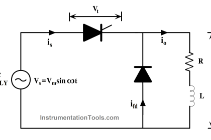
A single-phase half-controlled rectifier is similar to an uncontrolled rectifier. The difference between the circuit is the device used between source to load. In a controlled rectifier, Thyristor is used to control the voltage from zero to Maximum. The source voltage is controlled using the thyristor.
In this article, the source voltage Vm sinwt is fed to the Resistive load through the thyristor. The thyristor is a unidirectional device, the device is conducted when the anode is positive with respect to the cathode.
Moreover, the current flow takes place only when the device is triggered. The device can be triggered with firing angle α. Once the device triggered after the delay angle the device is starts conducting.
The output voltage Vo starts to rise from zero to Vmsinα. Since the load used in the article is Resistive load, therefore the io is in phase with Vo.
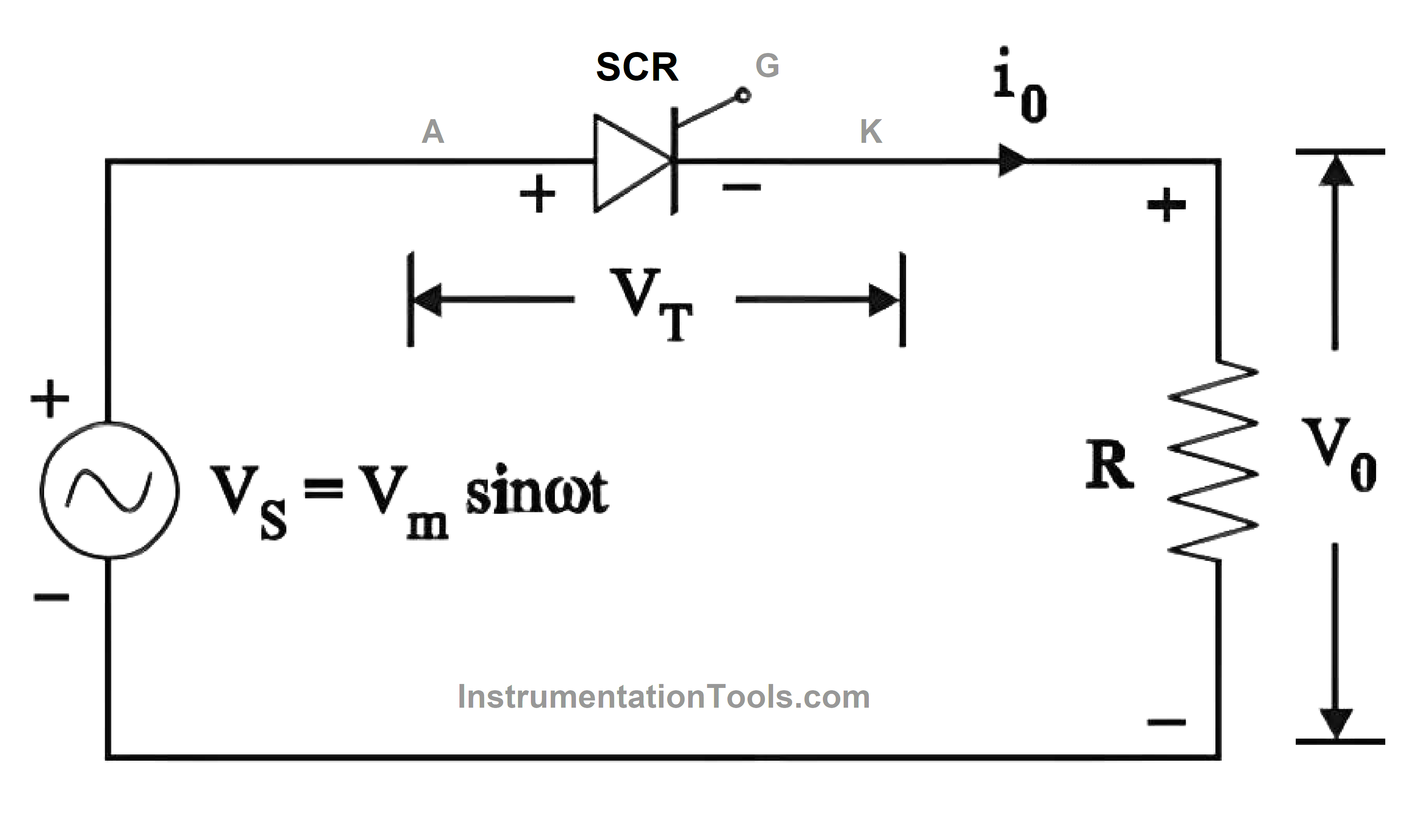
Fig. 3. Single Phase Half Controlled Rectifier
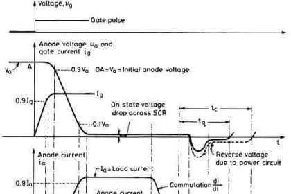
The firing angle of a thyristor, also known as the conduction angle or delay angle, is the angle in electrical degrees between the instant at which the voltage across the thyristor becomes positive and the instant at which the thyristor starts conducting.
In simple terms, it is the angle at which the thyristor is triggered into the on state during each cycle of alternating current (AC) voltage. The thyristor is triggered at every zero crossing of the input source.
When the SCR is turned on, load current flows until it is turned off by voltage reversal at wt= p, 3p, etc. Load current drops to zero at these angles, and the device is shut off shortly after the supply voltage reverse biases the SCR.
The phase relationship between the start of the load current and the supply voltage can be changed by adjusting the firing angle; thus, the term phase control is used for such a way of managing the load currents.
A single-phase half-wave circuit generates only one pulse of load current per source voltage cycle. A single-phase half-wave thyristor circuit is represented by the circuit. The thyristor conducts from wt = α to p, (2p+α) to 3 p, and so on. Load voltage V0 = 0 during the firing angle delay, whereas V0 = Vs during the conduction angle (p -α).
The average load voltage declines from the maximum to zero as the firing angle increases from zero to p. In Fig.4, the variation of voltage across the thyristor is also depicted as VT.
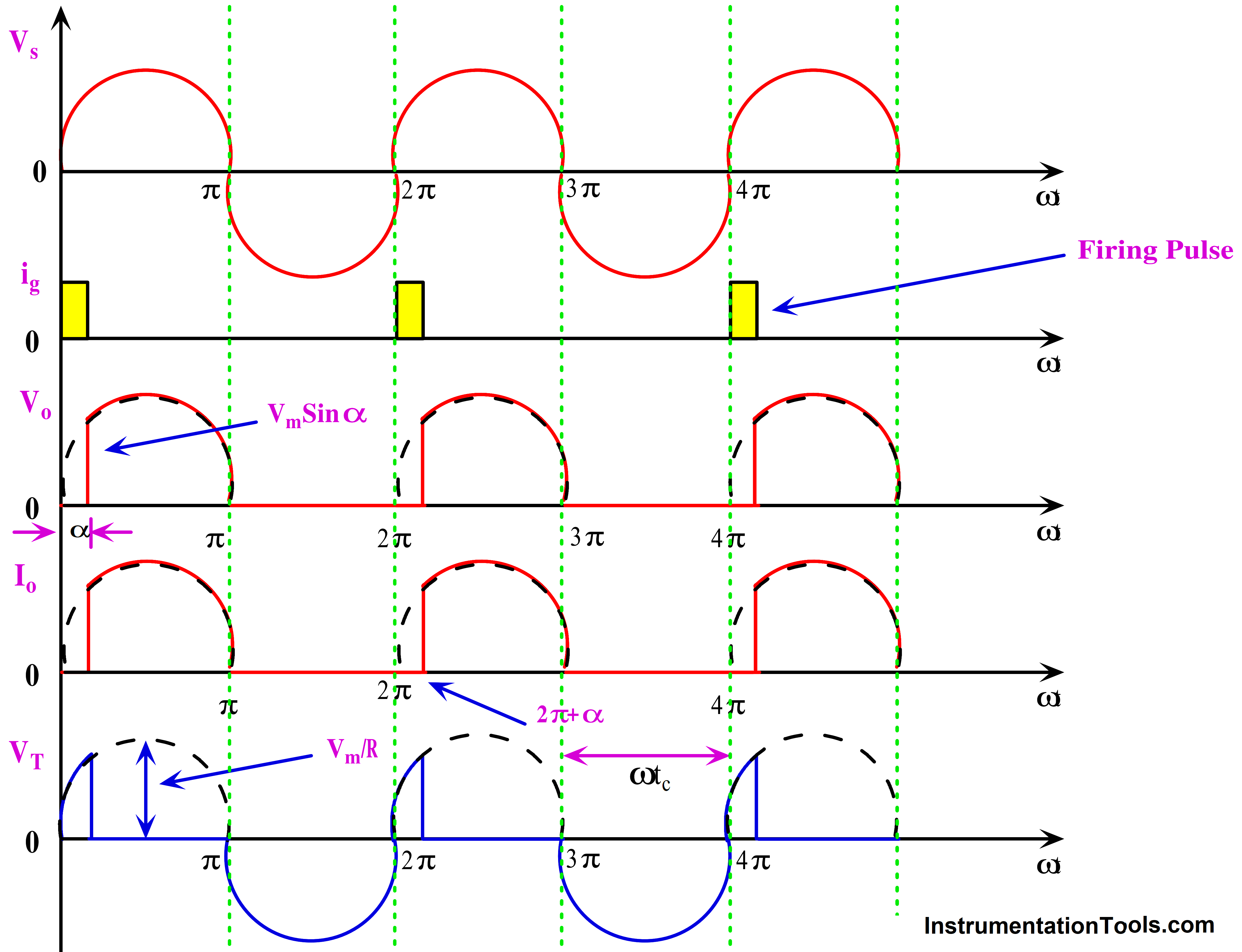
Fig. 4. Half Controlled Rectifier Output
Thyristor remains on from wt = α to p, (2p + α) to 3p, and so on, with VT = 0 during these periods. It is off from p to (2p + α), to (4p + α ), and so on; throughout these off intervals, VT has the supply voltage Vs waveshape. It is possible to see that VS= Vdc + VT.
The Circuit turn off time tc=p/w
Where w =2pf and f is the supply frequency in Hz.
The average voltage VO across load R for the single-phase half-wave circuit is given by
The maximum value of Vdc is obtained at α = 0o
The RMS Voltage of the single-phase half-controlled rectifier is obtained
Matlab Simulation Results
Matlab source code for half-controlled rectifier with R load
% Parameters

Vrms  =   230;            % RMS value of input AC voltage (in volts)

Frequency  =  50;       % Frequency of the input AC voltage (in Hz)

R  = 10;                       % Load resistance (in ohms)

T   =  1/Frequency;     % Time period of the input AC voltage (in seconds)

Vm   =  Vrms*sqrt(2);  % Peak value of the input AC voltage (in volts)

alpha   =   30;              % Firing angle (in degrees)

% Time vector

t   =   0:0.0001:T;

% Calculate the firing angle in radians

alpha_rad   =   alpha * pi / 180;

% Calculate the input AC voltage waveform

Vin   =   Vm * sin(2*pi*Frequency*t);

% Half-controlled rectifier operation

Vo   =  zeros(size(t));

Vo(t <= alpha_rad/Frequency)  =  Vm * sqrt(2) * sin(alpha_rad);

Vo(t > alpha_rad/Frequency)   =  Vm * sqrt(2);

% Calculate the output voltage waveform

Vout   =  Vo .* sin(2*pi*Frequency*t);

% Plot the input and output waveforms

% Plotting the waveforms

figure;

subplot(2,1,1);

plot(t, Vin, 'b', t, Vo, 'r');

title('Input and Output Voltages');

xlabel('Time (s)');

ylabel('Voltage (V)');

legend('Input Voltage', 'Output Voltage');

subplot(2,1,2);

plot(t, Io, 'g');

title('Output Current');

xlabel('Time (s)');

ylabel('Current (A)');
Matlab Simulink Circuit of Half-controlled Rectifier With R Load
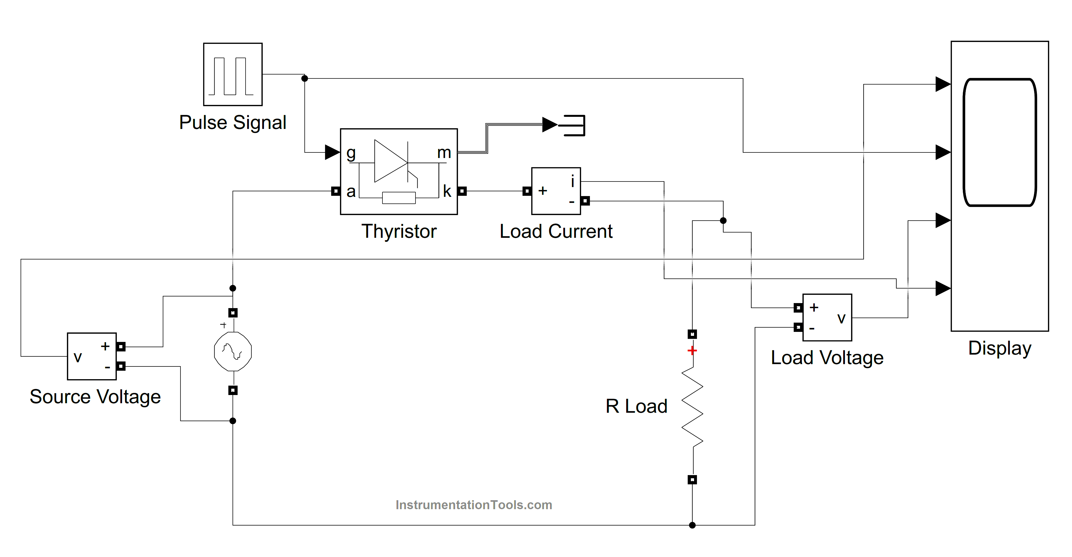
Fig.5. Simulink Circuit of Half-controlled Rectifier With R Load
Simulink Result
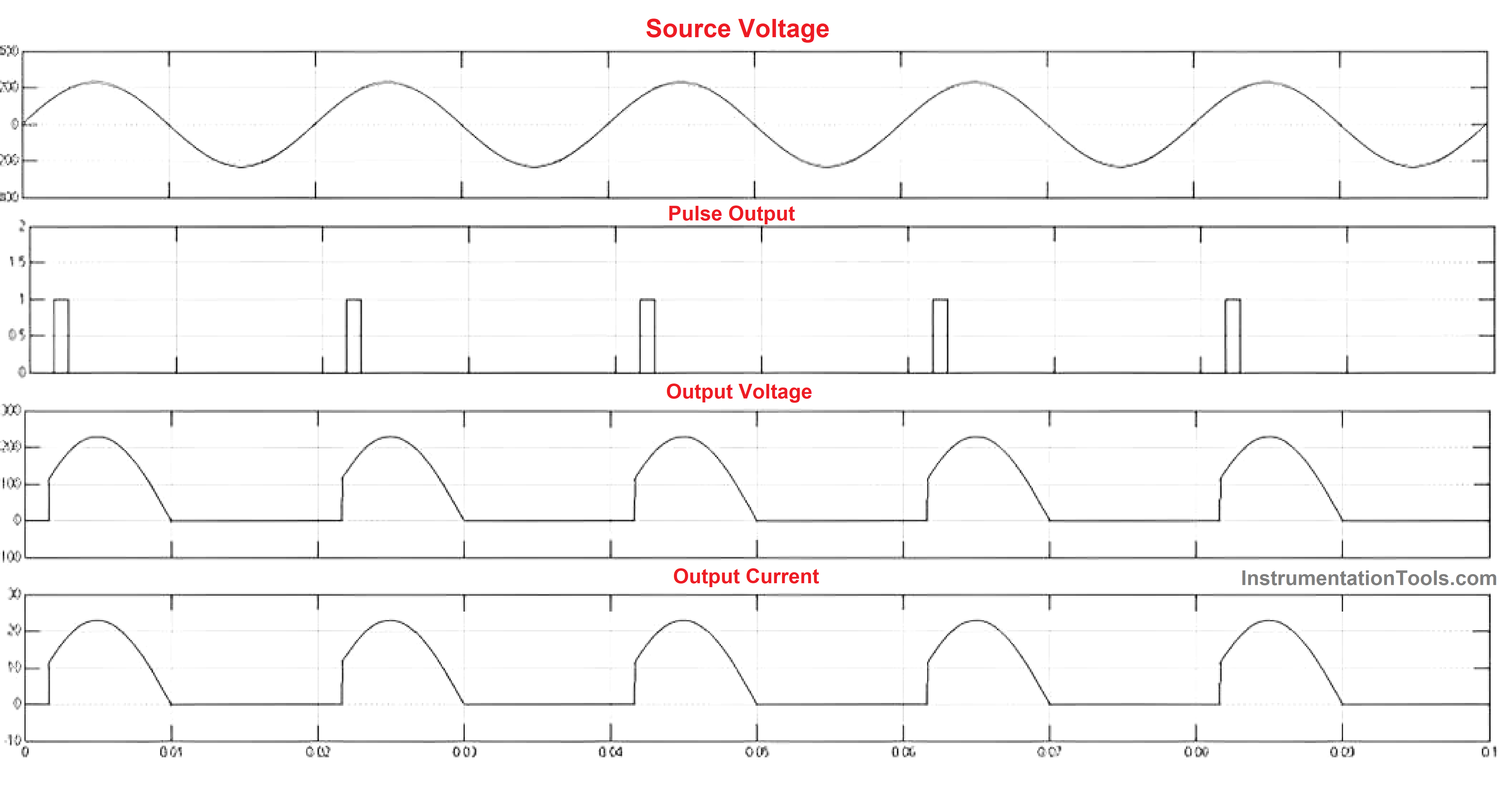
Fig.6. Simulink Response of Half-controlled Rectifier With R Load
Reference
- “Power Electronics” P. S. Bimbhra, Khanna Publishers, 2012
- “Power Electronics: Circuits, Devices and Applications”, M H Rashid, Pearson Education
- “Power Electronics”, M-Scheme, K.V. Kandasamy, 2020.
- https://in.mathworks.com/matlabcentral/fileexchange/90681-single-phase-half-wave-controlled-rectifier-with-resistance
If you liked this article, then please subscribe to our YouTube Channel for Instrumentation, Electrical, PLC, and SCADA video tutorials.
You can also follow us on Facebook and Twitter to receive daily updates.
Read Next:
- Thyristors Turn ON Methods
- Thyristor History, Types, Principle
- IGBT Characteristics & Advantages
- Power Electronic Devices Specifications
- Power Diode Characteristics & Advantages