Process Control Instrumentation monitors the state of a process parameter, detecting when it varies from desired state, and taking action to restore it.
Process Control
Control can be discrete or analog, manual or automatic, and periodic or continuous. Some terms that are commonly used in describing control systems are defined below.
Process Variable
The process variable is the parameter that is to be controlled.
Examples of process variables in control systems are the temperature measurement in a location, the pressure produced by a cooling water pumping system, or the voltage maintained by a standby generator.
To be controlled, the process variable must be capable of being measured and that measurement converted into a signal that can be acted on by the controller.
Sensors or Transducers
Devices that measure process variables are transducers or sensors.
Examples are a pressure switch that closes a set of contacts when air pressure in a supply line drops below a set value, or a watt transducer that converts a measurement of the electrical power produced by a generator into a low current signal proportional to power.
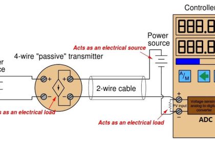
In many cases, the process variable sensor consists of a direct measurement device, called an element and a separate signal processor called a transmitter.
An example of this would be temperature measurement using a resistive temperature detector, or RTD, as the element and a temperature transmitter, which converts the varying resistance value of the RTD into a current or voltage proportional to the temperature.
Setpoint
The setpoint is the desired value of the process variable, normally preset into the control system by an operator, or derived as an output of another control calculation. The error signal is the difference between the process variable and the setpoint, and is the basis for control action.
The controller is the device that processes the error signal, determines the required control action, and provides a control output to the process.
Control Output or Manipulated Variable
The control output usually must act on the system through another device to effect the desired control action, such as varying the position of a valve, the speed of a motor, or the current through a heating element.
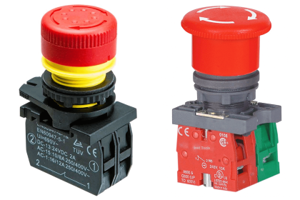
The device that converts the control output into control action is the actuator (in case of valves).
Discrete control
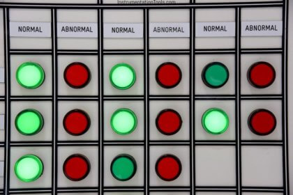
Discrete control deals with systems in which each element can only exist in certain defined states.
An example of discrete control would be starting an exhaust fan when the temperature in a space exceeds a preset value and stopping the fan when the temperature falls below a lower preset value.
The temperature (process variable) is either within the acceptable range, or outside of it. The fan control relay (actuator) is either on or off. This type of control is implemented with logic diagrams and circuits. In discrete control, even though some of the parameters actually have a continuous range of values, the only information used by the control system is whether their value is greater than, less than, or equal to some desired value.
A block diagram of a simple discrete control system is shown in below figure. The devices used to sense system conditions in discrete control are typically electrical switches, with contacts that are open when the variable is in one state and closed when it is in the other.

Figure : Discrete control system block diagram
Similarly, the control action is typically produced by control relays, which open or close contacts in the control circuits of motors, valve actuators, or other devices.
Analog control
Analog control deals with systems in which variables can have a continuous range of values, rather than simply discrete states. Basic analog control consists of the process of measuring the actual output of a system, comparing it to the desired value of that output, and taking control action based on the difference to cause the output to return to the desired value.
This process can be as simple as the driver of an automobile comparing the speedometer reading (process variable) to the speed limit (setpoint) and adjusting the position of the accelerator pedal (control action) to speed up or slow down the vehicle accordingly.
In most systems we are concerned with, this type of control action is performed automatically by electronic processors, which receive signals from sensors, process them, and provide signals to pumps, valves, motors, or other devices to effect control action. The below figure shows a block diagram of a basic analog control system.

Figure : Analog control system block diagram
Types of Analog Controllers
Analog controllers can be classified by the relationship between the error signal input to them and the control action they produce:
Proportional (P) controllers
Proportional (P) controllers produce an output that is directly proportional to the error signal.
A defining characteristic of P control is that the error signal must always be non-zero to produce a control action; therefore, proportional control alone cannot return the process to setpoint following an external disturbance. This non-zero error signal that is characteristic of P controllers is the steady-state offset.
The adjustable value of the proportionality constant of a P controller is the gain. The higher the gain, the greater the control action for a given error signal and the faster the response.
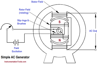
An example of a P controller is a governor on an engine-generator operating in droop mode, in which the governor opens the fuel valve proportionately to the difference between the desired revolutions per minute (RPM) setpoint and actual RPM; as load on the generator increases, RPM decreases and the governor increases the fuel flow to allow the engine to carry the additional load.
Similarly, as load decreases, RPM increases and the governor responds by reducing fuel flow to match the new load condition. For any condition other than noload, the actual RPM will be slightly different from the setpoint RPM (steady-state offset).
Proportional plus Integral (PI) controllers
Proportional plus Integral (PI) controllers produce a control action that is proportional to the error signal plus the integral of the error signal. The addition of the integrator allows the controller to eliminate the steady state offset, and return the process variable to the setpoint value.
The adjustable value of the integration constant of the PI controller is called the reset, because it has the effect of resetting the error signal to zero. An engine governor operating in isochronous mode, in which constant RPM is maintained over the full load range, uses PI control to accomplish this.
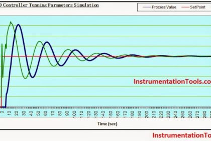
Proportional plus Integral plus Derivative (PID)
Proportional plus Integral plus Derivative (PID) controllers add a component of control action that is proportional to the derivative of the error signal, or the rate at which the error signal is changing.
This mode of control allows the controller to anticipate changes in the process variable by increasing control action for rapid changes, making it useful for systems that require very fast response times, or are inherently unstable without the controller. The adjustable value of the derivative constant in a PID controller is the rate.
Control Loops
The complete control scheme required to control a single process variable or a group of related process variables is called a control loop. The control loop includes the relevant part of the process, the process variable sensor and associated transmitter(s), the input signals, the controller, the control output signal, and the actuator.
Once defined, the control loop serves as the basis for both labeling of devices and documentation of wiring and control strategy. The process of adjusting the gain, reset, and rate parameters to obtain effective and stable response of the system to changes in the setpoint or external disturbances is called loop tuning, and is an essential aspect of control system startup and commissioning.
Types of Controllers
Control can be implemented using either individual standalone controllers, known as single-loop controllers, or by combining multiple control loops into a larger controller.
Single-loop controllers have provisions for a process variable input signal, a control output signal, setpoint adjustment, tuning of the PID control parameters, and typically include some type of display of the value of the process variable and the setpoint. They are compact, panel mounted devices that may be used effectively when only a small number of control loops is involved.
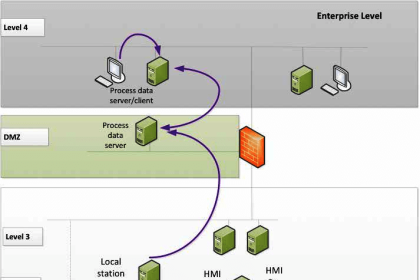
The basic controller used in control systems should be programmable logic controllers (PLCs), which are microprocessor-based systems having provisions for multiple inputs and outputs, both discrete and analog control capability, advanced human-machine interfaces (HMIs), and network communications capability.
Reference : This material adapted from the “Department of the Army, TM 5-601, Supervisory Control and Data Acquisition (SCADA) Systems for Command, Control, Communications, Computer, Intelligence, Surveillance, and Reconnaissance (C4ISR) Facilities, 21 January 2006.”
Read Next:
- PID Controller Multiple Choice
- What is Cascade Control Loop
- Industrial Instrumentation Quiz
- Basic Process Control System
- How to Select a PID Controller