Before my first site commissioning, I thought PLC programming was mainly about logic – timers, interlocks, sequences, and HMIs. Then I went to an actual plant. Commissioning is where theory meets reality. Sensors are wired by different technicians, panels are installed months after design, drawings are outdated, and production pressure is already high.
After Commissioning 20+ PLC Projects

At the site, you don’t just program a PLC; you understand machines, electricians, operators, noise, grounding, and human behaviour all at once. After working on more than 20 PLC commissioning projects, I realized that the real learning never came from software manuals. It came from troubleshooting at midnight, tracing cables inside hot panels, and explaining to operators why a bypass wire is not a permanent solution. Here are some lessons the site taught me, not the textbooks.
Drawings are never 100% correct
In the office, drawings look perfect. In plants, reality edits them. During commissioning, you quickly discover that field wiring rarely matches the schematic exactly. A proximity sensor may be wired to the next terminal, cable numbers may be swapped, spare cores get used without updating drawings, and sometimes an electrician connects a device to the nearest available terminal just to complete work on time. If you fully trust the drawing, you will waste hours debugging your PLC program for a problem that actually exists in the panel. The input looks ON in software, but the real sensor is not even connected to that channel.
Practical solution:
Before opening your programming software, verify signals physically. Use a multimeter, check 24V at the sensor, actuate the device manually, and watch the PLC input LED. Trace the wire from the field to the terminal to the I/O card. Mark corrections and update drawings immediately to avoid future confusion.
Most PLC faults are actually wiring faults
When a machine behaves illogically, the first instinct is to blame the program. But in real commissioning, the PLC is rarely the culprit. Loose terminals, broken ferrules, wrong polarity, mixed commons, damaged cables, and floating neutrals create strange symptoms like inputs flicker, outputs chatter, motors start randomly, or interlocks fail only sometimes. The logic is correct; the signal reaching the PLC is not. You may rewrite the program ten times, but the issue disappears the moment a terminal screw is tightened.
Practical solution:
Do not immediately modify logic. First, observe the I/O LEDs on the PLC card. If the LED itself is unstable, the problem is electrical, not software. Tighten terminals, check common wiring, verify polarity, and perform a gentle pull-test on wires. Always inspect panel wiring before changing code.
Earthing is not a formality, but the system’s nervous system
Many panels are commissioned with perfect wiring and a correct program, yet the system behaves unpredictably. Inputs turn ON without reason, analog values fluctuate, VFDs trip, and communication randomly drops. The hidden cause is often poor or improper earthing. Without a proper reference to ground, electrical noise has nowhere to go. Motor switching, contactor coils, and VFDs generate disturbances that travel into signal cables and PLC inputs. The PLC is not malfunctioning; it is reacting to electrical noise. Good earthing stabilizes the entire automation system.
Practical solution:
Create a clean, single-point earth for the control panel. Separate the power earth and the instrument earth. Connect cable shields only from one side (usually panel side). Avoid sharing the earth with heavy motors or welding machines. Check earth resistance and ensure tight earth busbar connections before troubleshooting software.
Simulation success means nothing
A PLC program that works perfectly in simulation can still fail on the real machine. In simulation, motors don’t create electrical noise, solenoid coils don’t produce voltage spikes, sensors respond instantly, and no one presses two pushbuttons together. But on site, contactors bounce, feedback delays, cylinders move more slowly, and operators act unpredictably. The sequence that looked smooth on a laptop may oscillate, skip steps, or trip interlocks in real operation.
Practical solution:
During commissioning, test every sequence physically. Add small delays, input filtering, and feedback confirmations instead of assuming ideal responses. Simulate real conditions like rapid start/stop, power loss, and simultaneous commands. Write logic expecting imperfect devices, not perfect simulation behaviour.
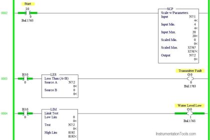
Analog signals teach humility
Digital signals are simple – ON or OFF. Analog signals live in the real world. During commissioning, you’ll see temperature jumping ±5°C without reason, flow showing values with no flow, and pressure drifting slowly even when the line is steady. The PLC program is correct, yet readings are unstable. The real causes are noise, improper shielding, long cable routes, ground loops, or wrong scaling. Most commissioning time is spent on analog signals, not sequence logic.
Practical solution:
Verify transmitter power supply, polarity, and reference ground. Use shielded twisted pair cable and ground the shield at one end only. Check the raw mA value before scaling in the PLC. Add filtering or averaging in logic, and confirm calibration at the instrument, not just on the HMI.
Operators will use the machine in ways you never imagined
While designing logic, we assume operators will follow instructions. In real plants, production pressure changes behaviour. Selectors are left between positions, pushbuttons are held continuously, sensors are blocked to avoid stoppage, and sometimes manual bypass wires appear to keep the machine running. The PLC program that worked during testing starts behaving strangely because it was written for ideal usage, not real human actions. Good automation must handle human unpredictability.
Practical solution:
Design defensive logic. Detect sensor bypass, add plausibility checks, require feedback confirmations, and prevent continuous start commands. Use alarms and clear messages instead of silent failures. Assume incorrect operations will happen and make the machine fail-safe rather than fail unpredictably.
Communication networks fail silently
When a normal input fails, you immediately get an alarm. When a network fails, the PLC often keeps running with wrong data. In remote I/O, drives, or SCADA communication, packets may freeze while the last value remains in memory. The system appears healthy, but interlocks are acting on stale information. This is more dangerous than a hard trip because operators trust the screen. Many commissioning issues are actually communication timeouts, not logic errors.
Practical solution:
Always monitor communication status bits or heartbeat signals. Create alarms for I/O module faults, data timeout, and connection loss. Never use network data directly in safety or critical interlocks without validity checks. If communication is lost, force the system to a defined safe state.
Interlocks are more important than sequences
Engineers spend most of their time perfecting the sequence – which motor starts first, delays between steps, and automatic cycles. But machines rarely fail because the order was wrong. Failures happen when protection is missing. A pump starts without water, a conveyor runs while jammed, or a heater energizes without airflow. The sequence worked exactly as programmed, yet the equipment got damaged because safety conditions were not verified. A good sequence runs the machine. Good interlocks protect the machine.
Practical solution:
Before writing sequence logic, define protection logic. Add permissives such as pressure, level, feedback, and temperature conditions. Every output should have at least one safety confirmation. If any critical condition is missing, prevent start and clearly alarm the operator instead of allowing operation.
First startup is not the real test, but a 2 AM operation is
During commissioning, everything works because engineers are standing near the panel. The real test begins when the plant runs continuously without supervision. At night, temperature changes, voltage fluctuates, equipment heats up, and small issues accumulate. Timers drift, sensors behave differently, and minor wiring problems finally appear. Many systems pass day trials but fail during continuous unattended operation.
Practical solution:
After commissioning, monitor the system for long-duration running. Check trends, alarm history, and fault logs the next day. Observe behaviour during temperature and load changes. Fine-tune timers, filters, and interlocks based on actual operation, not just short testing periods.
The best troubleshooting tool is still a multimeter
Modern PLC software provides online monitoring, diagnostics, and trending. Yet on-site, many problems cannot be solved from the laptop alone. Voltage drops, floating commons, missing supply, broken wires inside insulation, and weak contact points will all look like logic issues in the program. You may stare at the screen for an hour while the real answer is a missing 24V at a terminal. Commissioning repeatedly proves that electrical reality comes before software.
Practical solution:
Before deep program analysis, measure. Check supply voltage, continuity, and signal levels directly at the terminals. Compare the field voltage with the PLC input status. Follow a simple rule that if the physical signal is wrong, software cannot fix it. Verify electrically first, then debug logic.
In this way, we saw the things I learnt only after commissioning 20+ PLC projects.


Things after 20 plus commissioning experience