In industry, there are many pneumatic applications used. Some applications are small, and some applications are complex. Speed control of the pneumatic cylinder is an important factor in pneumatic applications. In some applications, fast or slow fixed speeds are not enough and need to control the speed. In some applications, fast speed is not satisfying the application so need to control the speed. So, use the speed control valve in the application and control the speed.
Speed Control of Pneumatic Cylinder
Solution
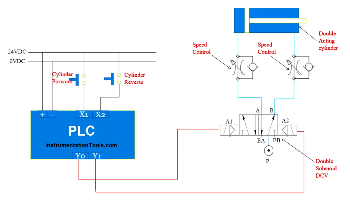
Here we need to take one example for the application so we can understand it easily. As shown in the figure we took two push buttons for forward and reverse operation.
PLC is used to control the outputs. Here we used a double solenoid direction control valve for the forward and reverse operation of the pneumatic cylinder. Once the user presses the forward button then the cylinder will move forward. If the user presses the reverse button then the cylinder will move reverse.
Here we used PLC for output control so needed to write a program in PLC according to the application. Without a speed controller cylinder speed is not controlled so add a speed control valve on both sides so we can control the speed of the pneumatic cylinder.
It is always necessary to reduce the speed of the cylinder from the maximum speed based on the selected size of the final control valve to the nominal speed depending on the application.
Speed control of Pneumatic Cylinders can be conveniently achieved by regulating the flow rate of supply or exhaust air.
The volume flow rate of air can be controlled by using flow control valves which can be either Two-way flow control valves or One-way flow control valves.
PLC Programming
Here we can write a PLC program for forward/reverse operation. And we can add a speed controller in the cylinder so we can control the pneumatic cylinder speed with the speed controller.
List of Inputs and Outputs
List of Inputs
X0: Cylinder Forward PB
X1: Cylinder Reverse PB
List of Outputs
Y0: Cylinder Forward
Y1: Cylinder Reverse
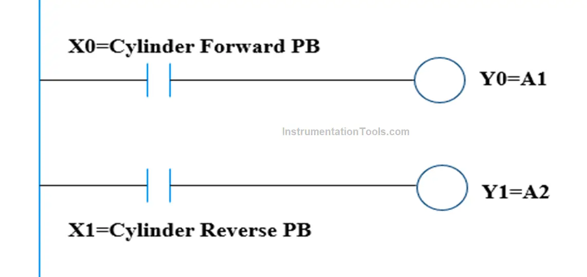
Ladder Logic Diagram for Operation of Pneumatic Cylinder
Program Explanation
In the first rung, we used NO contact of the Cylinder forward push button (X0) so the Cylinder forward (Y0) output can be operated with the forward push button (X0). Hence once you press the forward push button the output will give a signal to the solenoid A 1 and due to the mechanism direction control valve spooler will move and it will change the direction of the air. As shown in the figure, there is a speed controller in the circuit so as per requirement we can rotate the nob and control the forward speed.
In the second rung we have used NO contact of the Cylinder reverse push button (X1) so Cylinder reverse (Y1) output can be operated with the reverse push button (X1). Hence once you press the forward push button the output will give a signal to the solenoid A 2 and due to the internal mechanism direction control valve spooler will move and it will change the direction of the air. As shown in the figure, there is a speed controller in the circuit so as per requirement we can rotate the nob and control the reverse speed.
If you liked this article, then please subscribe to our YouTube Channel for Electrical, Electronics, Instrumentation, PLC, and SCADA video tutorials.
You can also follow us on Facebook and Twitter to receive daily updates.
Read Next:
- Pneumatic Valves and Cylinder Sizing
- Transferring Data Across PLC Systems
- Single-acting Pneumatic Cylinder Operation
- PLC Control of Two Outputs with one Input
- Simulation of Studio 5000 and FactoryTalk View