The recommended controller for SCADA systems is the programmable logic controller (PLC). PLCs are general-purpose microprocessor-based controllers that provide logic, timing, counting, and analog control with network communications capability.
Components of PLC
A PLC consists of the required quantities of the following types of modules or cards, mounted on a common physical support and electrical interconnection structure known as a rack.
A typical PLC rack configuration is shown in the below figure.
 Rack")
(1) Power supply :
The power supply converts facility electrical distribution voltage, such as 230 VAC, 120 VAC or 125 VDC to signal level voltage used by the plc processor and other modules.
(2) Processor :
The processor module contains the microprocessor that performs control functions and computations, as well as the memory required to store the program.
(3) Input/Output (I/O) :
These modules provide the means of connecting the processor to the field devices. Examples of these modules are Analog Input Module, Analog output module, Digital input module, Digital output module etc.
These are used to connect devices between plc and field devices like flow transmitters, pressure transmitters, control valves, analyzers, substation feeders for motor control etc.
(4) Communication :
Communications modules are available for a wide range of industry-standard communication network connections. These allow digital data transfer between PLCs and to other systems within the facility.
The most commonly used modules are Modbus communication cards or Serial communication.
Some PLCs have communications capability built-in to the processor, rather than using separate modules.
(5) Communication Media and Protocols :
The most common communication media used are copper-wire, coaxial, fiber-optics, and wireless. The most common “open” communication protocols are Ethernet, Ethernet/IP, and DeviceNet.
“Open” systems generally provide “plug and play” features in which the system software automatically recognizes and communicates to any compatible device that is connected to it.
Other widely accepted open protocols are Modbus, Profibus, and ControlNet.
(6) Redundancy :
Many PLCs are capable of being configured for redundant operation in which one processor backs up another.
This arrangement often requires the addition of a redundancy module, which provides status confirmation and control assertion between the processors. In addition, signal wiring to redundant racks is an option.

PLC Software and Programming
All software and programming required for the PLC to operate as a standalone controller is maintained on-board in the processor.
PLCs are programmed with one of the following standard programming languages:
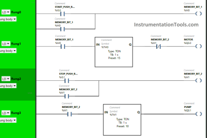
(1) Ladder Diagrams :
Used primarily for logic (Boolean) operations and is easily understood by electricians and control technicians. This is the most commonly used language in the United States and is supported by all PLC suppliers.
(2) Function Block Diagrams :
Used primarily for intensive analog control (PID) operations and is available only in “high-end” PLC’s. It is more commonly used outside the United States.
(3) Sequential Function Chart :
It Used primarily for batch control operations and is available only in “high-end” PLC’s.
(4) Structured Text :
It is Used primarily by PLC programmers with a computer language background and is supported only in “high-end” PLC’s.
SCADA
SCADA PLCs should be specified to be programmed using ladder diagrams. This language is very common, and duplicates in format traditional electrical schematics, making it largely understandable by electricians and technicians without specific PLC training.
The ladder logic functions the same as equivalent hard-wired relays. The PLCs in a SCADA system will be networked to one or more central personal computer (PC) workstations, which provide the normal means of human-machine interface (HMI) to the system.
These PCs will be provided with Windows-based HMI software that provides a graphical user interface (GUI) to the control system in which information is presented to the operator on graphic screens that are custom-configured to match the facility systems.
For example, the electrical system status may be shown on a one-line diagram graphic in which open circuit breakers are colored green, closed breakers are colored red, and voltage and current values are displayed adjacent to each bus or circuit breaker.
PLCs are recommended for the following reasons :
(1) They were developed for the factory floor and have demonstrated high reliability and tolerance for heat, vibration, and electromagnetic interference.
(2) Their widespread market penetration means that parts are readily available and programming and technical support services are available from a large number of control system integrators.
(3) They provide high-speed processing, which is important in generator and switchgear control applications.
(4) They support hot standby and triple-redundant configurations for high-reliability applications.
If you liked this article, then please subscribe to our YouTube Channel for PLC and SCADA video tutorials.
You can also follow us on Facebook and Twitter to receive daily updates.
Read Next:
- PLC Practice Questions
- Components of SCADA
- Relays in Ladder Logics
- Applications of SCADA
- SCADA Communication