S7-1200 PLC is a compact, modular, and cost-effective solution that offers a wide range of features and flexibility for small to mid-sized automation applications. These features include communication options, memory, CPU performance, and IOs configuration. When you have a process that you need to control, you should choose the PLC and configure it to best fit your process requirements.
In this article, we will discuss the hardware configuration of S7-1200 PLC and we will give an example of how to configure it in the Siemens Tia portal.
Contents:
- What is the hardware configuration of a PLC?
- Importance of hardware configuration.
- Simple project example.
- How to configure our PLC with the given example?
- Hardware configuration of CPU.
- IOs hardware configuration.
- HMI configuration.
- Conclusion.
What is the hardware configuration of a PLC?
The hardware configuration refers to the specific components of the PLC, such as the CPU, memory, input/output (I/O) modules, communication ports, power supply, and any additional modules or accessories that may be needed and added to the system.
The hardware configuration of a PLC also includes enabling or disabling some of the CPU features, depending on the device, its capabilities, and the requirements of your process.
The hardware configuration steps for a PLC typically involve the following:
- Select the appropriate PLC model based on the application requirements.
- Identify the input/output requirements for the system, which include the type and number of sensors, actuators, and other devices that will be connected to the PLC.
- Choose the communication protocol and network topology that will be used to connect the PLC to other devices and systems.
- Determine the power supply requirements for the PLC and its peripherals.
- Mount the PLC in an appropriate location and connect all the necessary cables and wires.
- Configure the PLC software to communicate with the hardware components and set up the appropriate logic and control functions.
The specific steps for hardware configuration may vary depending on the PLC model and the application requirements, but these are the basic steps that are typically involved in the process.
In this article, we will talk about the hardware configuration that is done in the TIA Portal platform. That means we will assume that you know your application and that you have already chosen your PLC model and the Power supply to feed it. You can refer back to previous articles where we discuss how to choose the PLC and power supply that best fits your application.
Importance of Hardware Configuration in PLC
Proper hardware configuration ensures the system is reliable and robust. If the hardware components are not configured correctly, they may not work as intended, resulting in system failures or errors
Hardware configuration affects the performance of the system. By choosing the right hardware components and configuring them appropriately, the system can operate at maximum efficiency and speed and can handle a high volume of inputs and outputs.
Hardware configuration impacts the scalability and flexibility of the system. The choice of hardware components and their configuration should take into consideration future expansion or modifications to the system, to ensure that the system can easily accommodate changes or upgrades.
Hardware configuration affects the cost of the system. By selecting the appropriate hardware components and configuration, unnecessary costs can be avoided, and the overall cost of the system can be minimized.
S7-1200 Hardware Configuration
We will assume a simple PLC project and see how we can configure the PLC into our project before we start writing our code.
Temperature Control System for a Reactor using PLC
The project involves controlling the temperature of a reactor using a PLC. The system should measure the temperature of the reactor and adjust the temperature by controlling the flow of a cooling fluid.
The project uses four thermocouples to measure the temperature, two solenoid valves to control the flow of the cooling fluid, and a motor to drive the impeller of the reactor.
I/O Configuration
Inputs:
Thermocouples 1 – 4: these are 4 analog inputs that measure the temperature at different locations inside the reactor.
Emergency Stop Pushbutton: This is a digital input that is used to stop the system in case of an emergency.
Temperature Set Point Potentiometer: This is an analog input that allows the operator to set the desired temperature setpoint.
Outputs:
Solenoid Valve 1 and 2: these are 2 digital outputs that control the flow of the cooling fluid through the reactor pipes.
Motor Control: This is a digital output that controls the speed and direction of the motor that drives the impeller.
Heater Control: This is a digital output that controls the heating system of the reactor.
System Operation:
- The system waits for the operator to set the temperature setpoint using the potentiometer.
- The PLC reads the temperature setpoint and compares it to the current temperature of the reactor, which is measured by the four thermocouples.
- If the reactor temperature is below the setpoint, the PLC activates the heater control output to increase the temperature.
- If the reactor temperature is above the setpoint, the PLC activates one of the solenoid valve outputs to increase the flow of the cooling fluid and decrease the temperature.
- The PLC continuously monitors the temperature and adjusts the heater and cooling systems to maintain the desired setpoint.
- The PLC also controls the motor that drives the impeller to mix the contents of the reactor.
- If the emergency stop pushbutton is pressed, the PLC deactivates all the outputs and stops the system.
The PLC project can be further expanded and modified to include additional functionality, such as alarms, data logging, or remote monitoring, depending on the specific requirements of the project. However, we will not care about coding the PLC logic of this system, rather we will use this example to explain how to hardware configure the PLC to fit our project.
This includes:
- Selecting the PLC CPU.
- Selecting the IO modules.
- Assigning the input and output tags to the hardware modules.
- Assigning an IP to the PLC for communication.
- Assigning a protection password.
- Configuring the local time of the PLC.
- Configuration the HMI and set the connection with PLC.
How to configure PLC with the given example?
Below we will discuss the basic PLC project creation with the required hardware.
The hardware configuration of the CPU:
Selecting the CPU:
When you start a new project in TIA Portal, you should configure a new device and add it to your project. See picture 1.
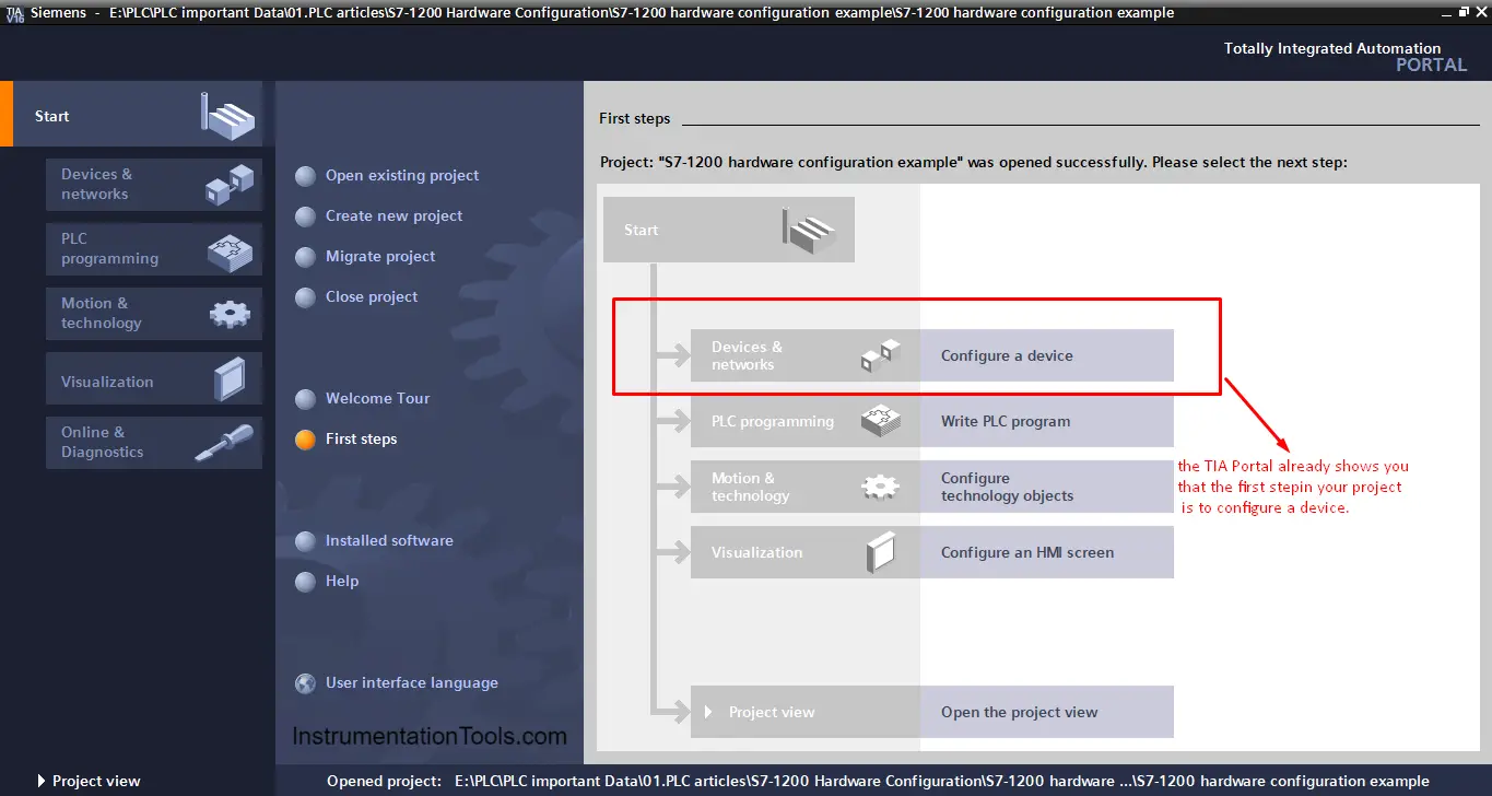
As you can see from the previous picture, the TIA portal already shows you that the first step should be configuring a new device.
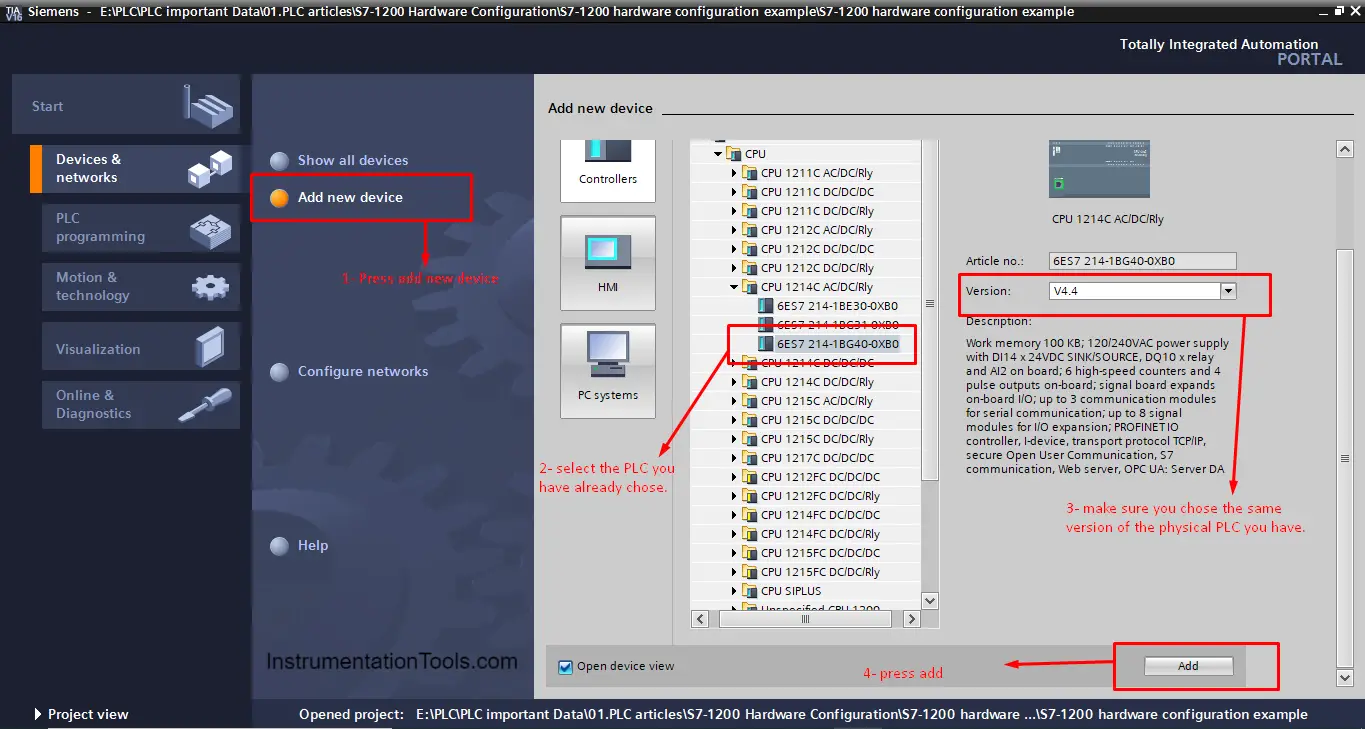
In the previous article, we discussed how to choose the PLC that fits your process, so we will not mention that here again, for our project as it is a simple project we will choose the CPU 1214C AC/DC/RLY. See picture 2.
CPU Properties:
Depending on the CPU that you have selected for your project, different CPU features and properties will be available.
You can enable or disable these features depending on your needs. Some of the features will need extra configuration to be made. See picture 3.
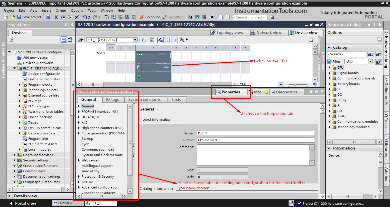
As you can see in the previous picture there are many properties that you can set for your CPU in the project.
We will mention some of these properties which you will need to configure in each project you make, some other properties are used only in special cases.
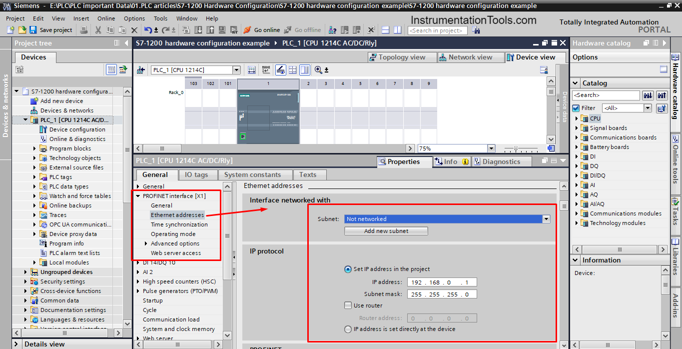
Communication:
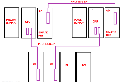
This is a very important configuration for any PLC project; your project will most probably have different modules and devices that need to talk to each other. Setting up the communication between your PLC and these devices is important for your project.
By selecting the CPU you already have defined how the communication will be. Some CPU only works with Profinet, some only work with Profibus and some have the ability to use both. The selected PLC for this example only works with Profinet.
From the Profinet interface you will set the IP address for your PLC, this IP should be unique in the project; you can’t use the same IP for two different modules. See picture 4.
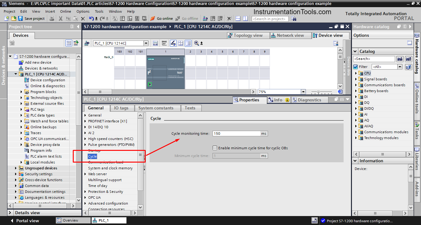
Cycle time:
This is another important property for your PLC, as you know; the cycle time of your program will depend on how much code you have written and how long it will take the PLC to execute this code.
In the cycle time properties, you can set the cycle monitoring time, if the PLC takes longer than this set time to execute the program, then the PLC will give an error. See picture 5.
From this property you can also determine the minimum cycle time for your CPU, you can do that if you triggered the “Enable minimum cycle time for cyclic OBs”.
You then can write the minimum cycle time that you want, and the PLC will adjust its performance to match this time. Off course this time is limited by the CPU performance capability, so you can’t lower this time below a certain limit.
System and clock memory bits:
System memory bits and clock memory bits are built-in bits inside the CPU that the operating system used to indicate certain events in the PLC.
For example, there is a memory bit that will change to TRUE only at first scan or a memory bit that will be TRUE if diagnostic status changes, there are also some dedicated clock memory bits like a bit representing a clock of 10Hz or a bit representing a clock of 2Hz.
These bits can be very useful in some applications and can save a lot of programming code to obtain the same functionality. See picture 6.
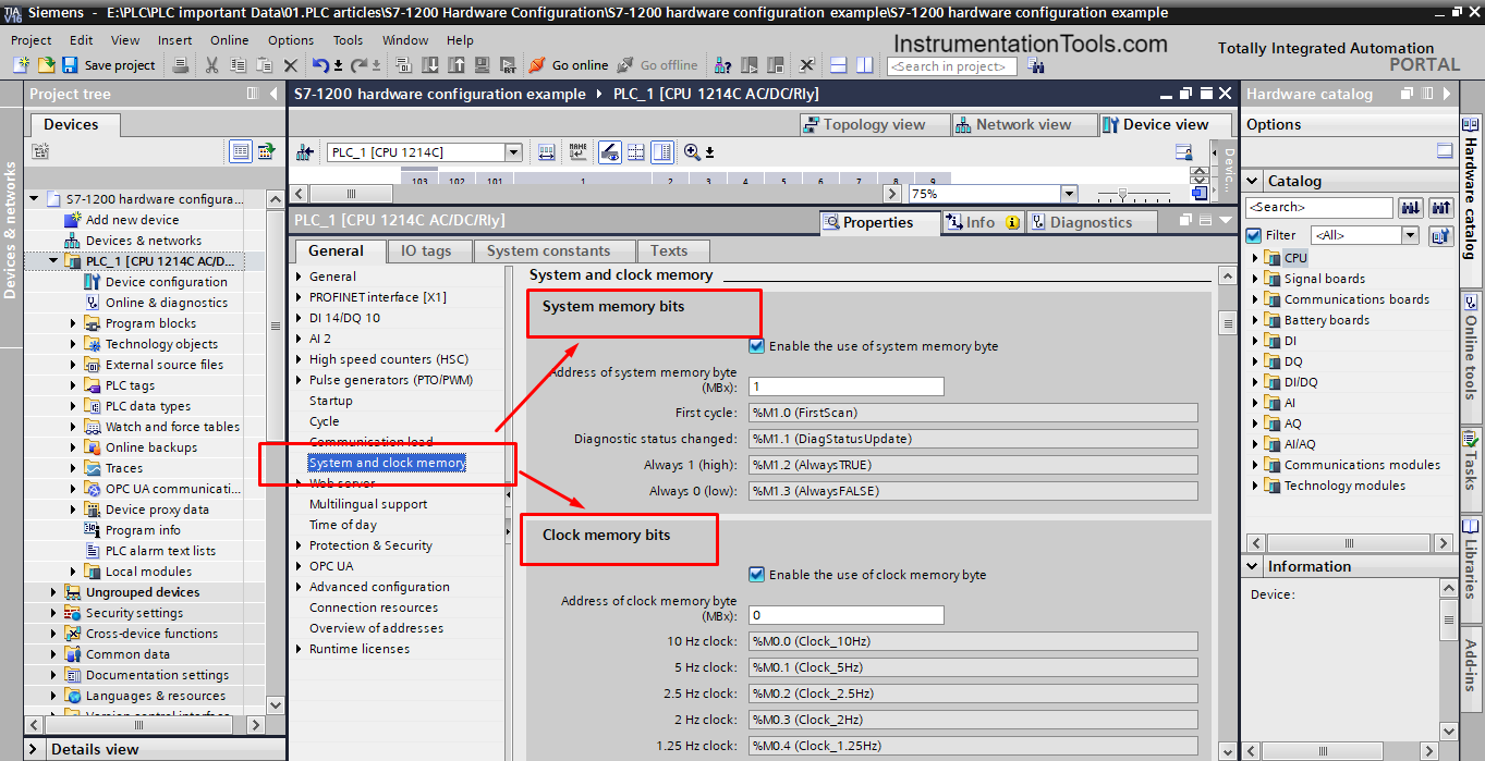
You can enable the use of one or both memory bytes; you can also determine the address of these bytes as you can see from the picture.
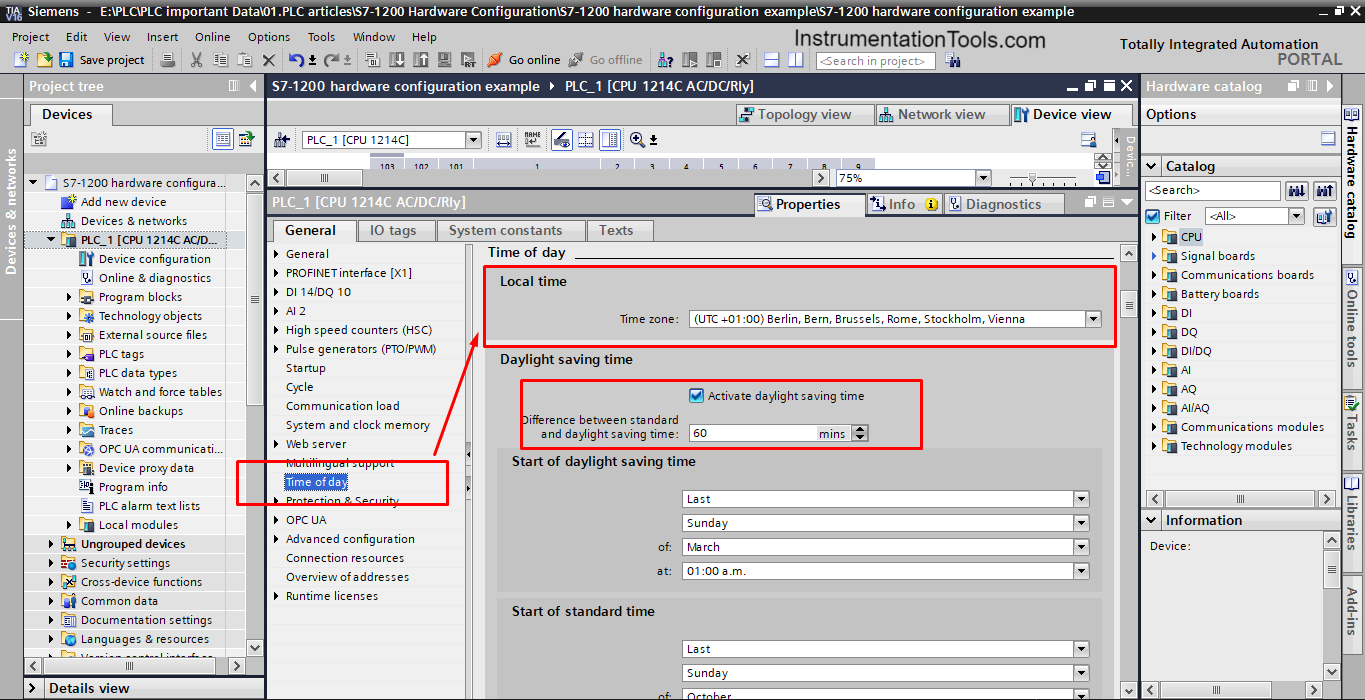
Time of Day:
Another very important property of your PLC is setting the time inside your PLC. In almost any project you make, you will need to know the real-time to be able to assign certain actions with different dates.
In the previous article, we talked about local and system times inside the PLC and how to use them. This property of the CPU allows you to set the local time to the time zone that you want. See picture 7.
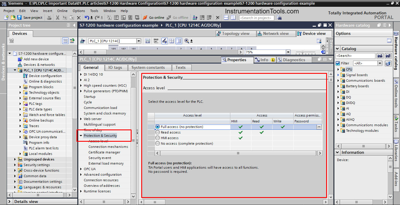
Protection and security:
From this property, you can determine the access level and password protection for your PLC. See picture 8.
The previously mentioned properties are the most commonly configured properties with almost any PLC project you would do. There are some other properties that are less likely to be used with simple programs such as Web servers and OPC UA.
The next step in the Hardware configuration of your project is configuring the IOs.
IOs hardware configuration:
Another important step of your project is the configuration of your IOs, which means deciding how many IO modules you need and what kind of IO modules you need.
When deciding about your IOs, you should consider some key points like having some spare IO points and choosing the IO modules that fit the input sensors and output actuators inside your project. See picture 9.
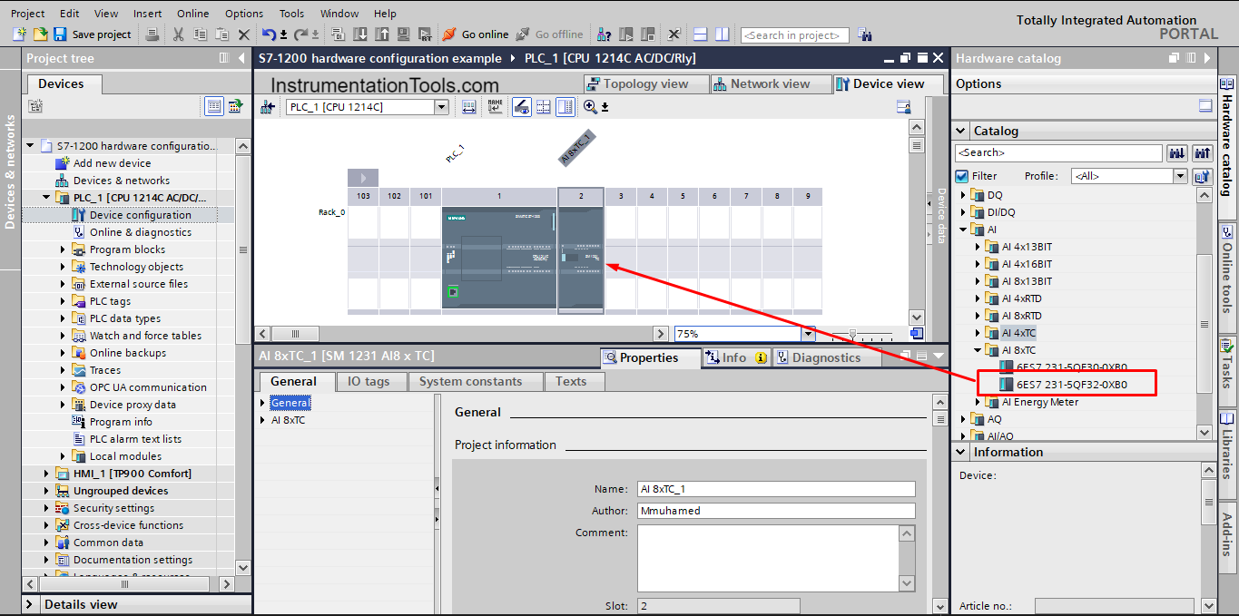
As we mentioned in our example project, we have 4 thermocouples used as analog inputs to my PLC, so I need to add an analog input module with at least 4 input channels because the selected PLC only has 2 analog input channels.
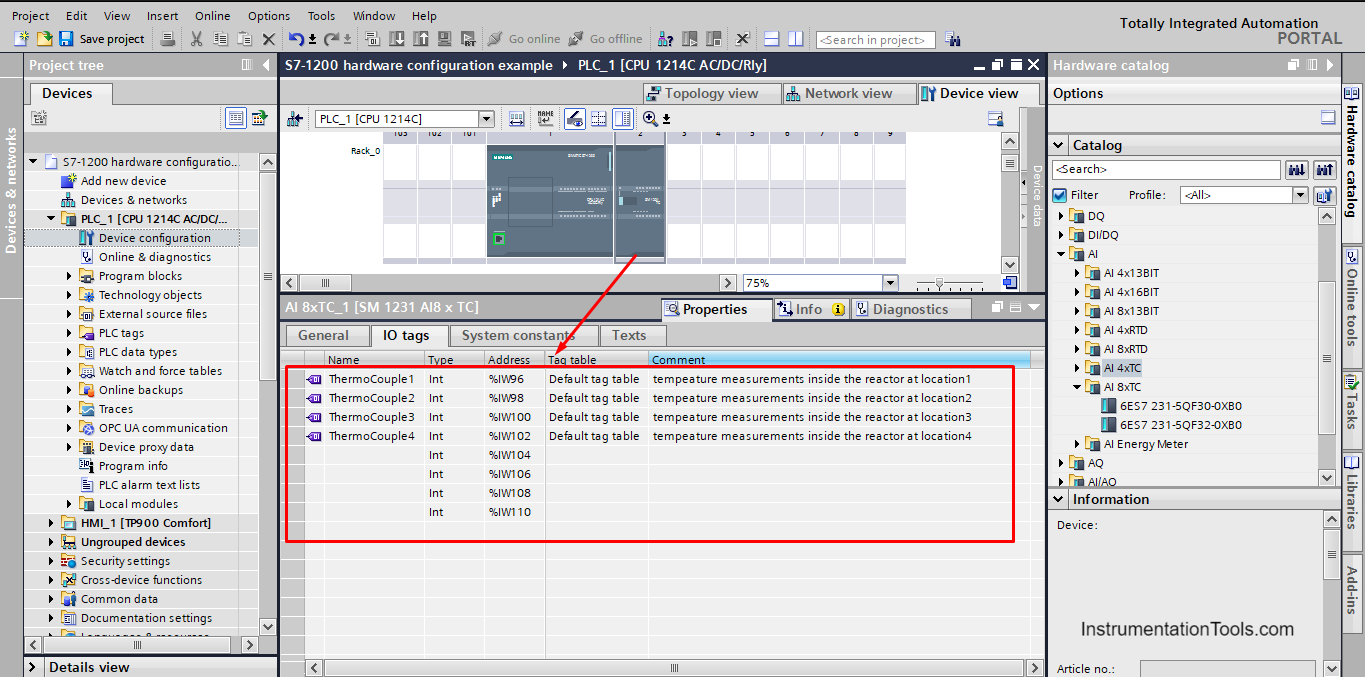
Another thing is that the thermocouple is a special type of analog input that requires a dedicated input module. That is why we chose the AI 8xTC module, which has 8 input channels dedicated to being used with thermocouples; we choose the 8-channel module and the 4 to have spare channels for future use in case we need to expand our project.
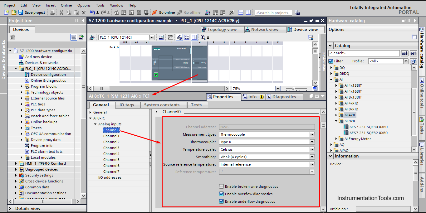
If you go to the properties of the AI 8xTC module you will see that you can configure each input channel individually, you can choose the type of thermocouple, scale of measurement, and other properties. See picture 10.
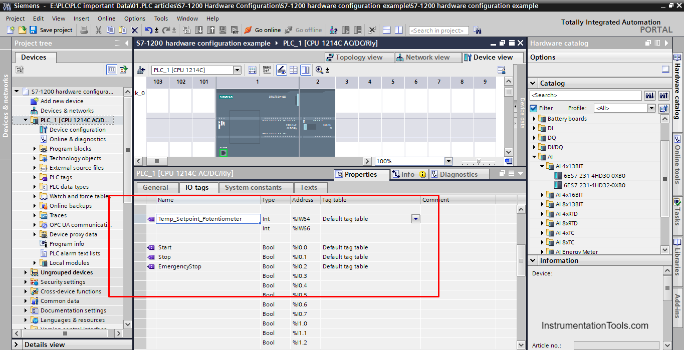
Next, you will need to define your IOs tags and assign each input or output you have to a proper IO point in your PLC or in the IO modules. See picture 11.
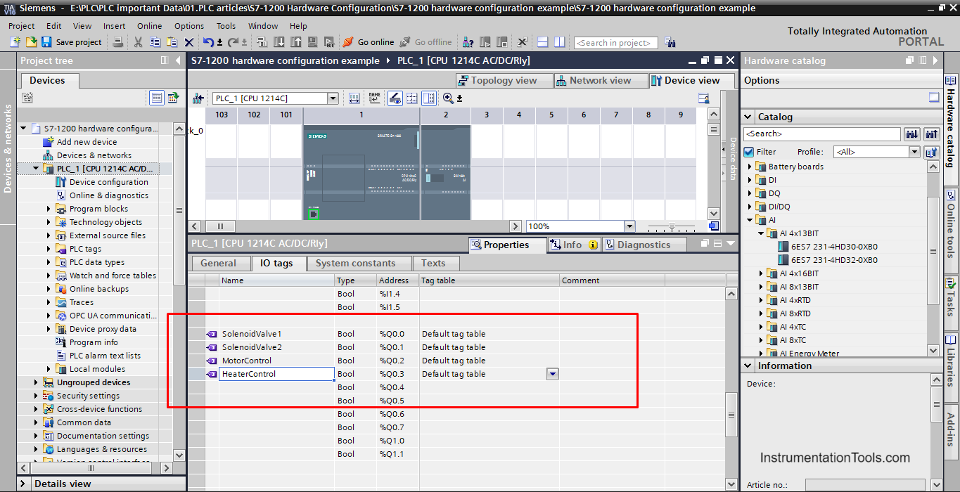
Then you continue to assign the rest of the inputs and outputs tags, see pictures 12 and 13.
HMI Configuration
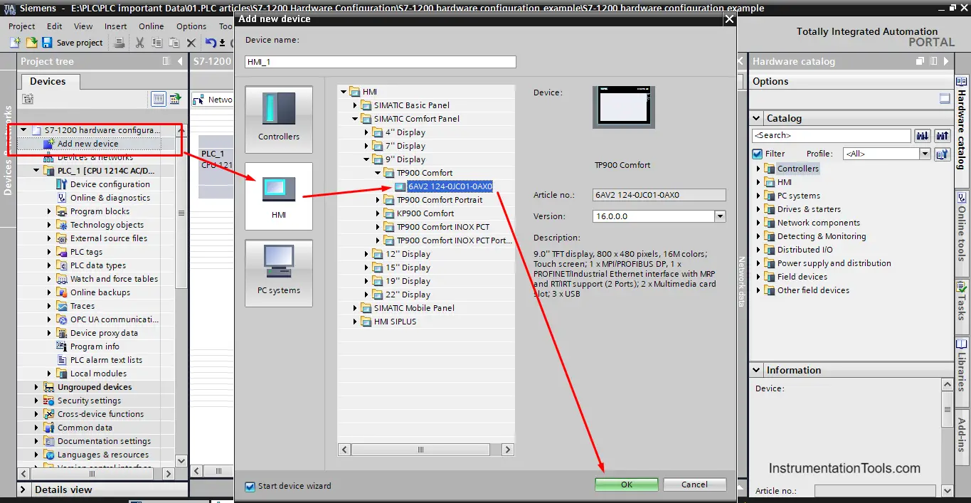
Your PLC project will probably need an HMI, after selecting your HMI there are different configurations you can make.
In this article, we will only show how to configure the communication between the HMI and the PLC. As you see from the previous picture, you select an HMI by adding a new device and then select an HMI. See picture 14.
There are different ways to set the communication between the HMI and the PLC, but the easiest way is through the network view page. See picture 15.
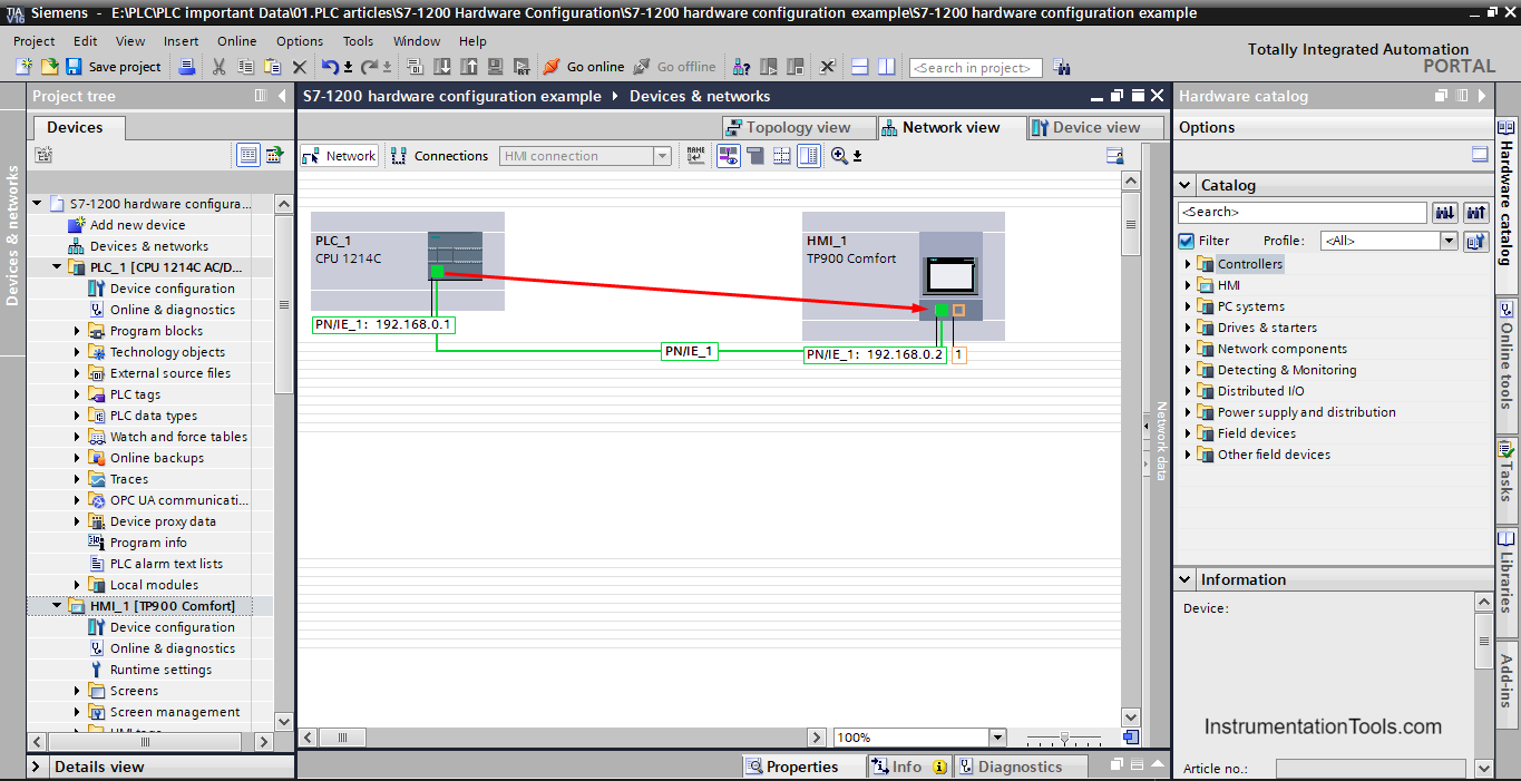
Inside the network view page, you can set the connection between the HMI and the PLC by simply clicking on the small green square representing Profinet from the HMI and dragging it to the PLC.
TIA Portal will then draw a green line between the two modules and it will automatically give the HMI an IP address to set the communication between them.
Downloads
Conclusion
- Hardware configuration is a very critical step of any PLC project.
- The proper hardware configuration of your PLC will ensure that the needed functionalities of the project are met.
- Hardware configurations include selecting IO modules, enabling or disabling certain CPU properties, and configuring different devices like HMI with your PLC.
If you liked this article, then please subscribe to our YouTube Channel for Instrumentation, Electrical, PLC, and SCADA video tutorials.
You can also follow us on Facebook and Twitter to receive daily updates.
Read Next:
- Types of SCADA System Architecture
- PLC Cold Standby and Hot Standby
- Compare Motion Controller & PLC
- Normally Closed For Stop Buttons
- Timers in Siemens PLC Programming