Thermocouple or resistance temperature detectors (RTDs) are used for measuring temperatures, we will discuss more how to install them and also on necessary precautions to be taken while doing the installation.
1) The total length of the sensitive measuring element, thermocouple, or RTD must be immersed in the heat zone to be measured.
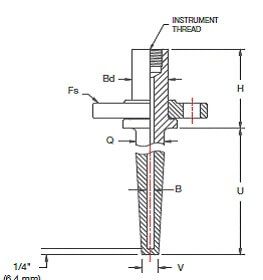
2) The immersion length needs to be equivalent to ten times the diameter of the Thermowell tube for protection. It is good by increasing this value where space allows for it.
For fluids in movement, the immersion lengths can be only six diameters, if the line and the outer part of the Thermowell are well insulated.
3) In small-sized lines where it is not possible to achieve the minimum length required, it is a common practice to insert it into an elbow of 45° to 90°. On the other hand, it is possible to enlarge the pipe section in the area of installation of the Thermowell. These procedures are normally necessary for pipes smaller than 4 “.
Installation of Thermocouple and Resistance Temperature Detector (RTD)
The sensor elements will be installed once the mechanical & process work has been completed. The sensor may damage if we install it before the completion of other departments’ works.
We need to check that the interior of the Thermowell is clean. Make sure it is free of foreign objects so that the sensor penetrates without difficulty until the end. It makes good contact with the bottom of the shell.
When connecting thermocouples, special care must be taken to ensure that the polarity of the extension coincides with that indicated on the head connection terminals. Through the proper color, coding will determine the polarity of the conductors.
In the same way, the polarity of the conductors in each joint will be verified, the most common in junction boxes that collect various thermocouple signals and to be grouped into a single multi-pair cable. Often the color codes of both cables correspond to standards different when connecting resistance thermometers.
Attention is to be paid in accordance with the Engineering schemes when the connection is three or four wires to the correct connection of each conductor.
Compensation and connection cables
Cables carrying thermocouple or resistance temperature detector (RTD) signals shall not run through other paths than those reserved for this purpose.
Also across not for those specifically reserved for electrical signals of instrumentation. Need to take care to avoid long runs parallel to power cables energy and minimize their crossovers.
In the case of thermocouples, a specific route will be preferred for extension cables, even considering their possible shielding if it is foreseen the risk of strong disturbances.
Thermocouples
a) Verification with a signal calibrator – Without disassembling the thermocouple
Disconnect the extension cables from the thermocouple head, connect a signal calibrator and verify the signal generated by it.
Known the process temperature, compare the reading obtained with the one indicated on the display for the type of thermocouple selected.
b) Verification with a signal calibrator – Without taking the thermocouple to the workshop
Disconnect the extension cables from the thermocouple head, extract the thermocouple from the sheath, connect calibrator of signals to the thermocouple, and by means of a lighter or similar heat the tip of the Thermocouple.
If the millivolt signal generated by the thermocouple rises, the thermocouple is in good condition.
c) Verification with a signal calibrator and heat bath or oven calibration in the workshop
Disconnect the extension cables from the thermocouple head, extract the thermocouple from the sheath and bring it back to the instrumentation workshop.
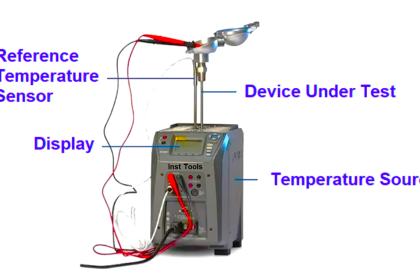
Place the thermocouple in a heating bath or calibration oven, and use a signal calibrator to verify that at different temperatures, the generated values correspond to those indicated by the signal calibrator for the type of thermocouple in question.
Obviously, if the thermocouple responds to the reference values, it is in good condition.
Resistance Temperature Detector (RTD)
a) Verification with an ohmmeter or signal calibrator – Without disassembling the RTD
Disconnect the connection cables from the resistance temperature detector’s head and check the resistance electrical of the same. Knowing the process temperature, compare the reading obtained with the table reference.
If the resistance read corresponds to the known process temperature, the resistance thermometer is in good condition.
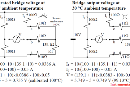
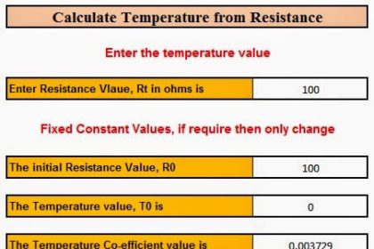
If the reference table is not available, it may be recalled that the value at 0 ºC is 100 ohms, and it varies practically linearly about 38.5 ohms per every 100 ºC.
b) Verification with an ohmmeter (or signal calibrator) – Without bringing the RTD to the workshop
Disconnect the connection cables from the resistance temperature detector’s head, remove the resistance temperature detector from the sheath.
Connect an ohmmeter to the resistance temperature detector, and heat its tip with a rubbing with hand or similar.
If the electrical resistance increases, the resistance thermometer is good.
c) Verification with an ohmmeter (or signal calibrator) and thermal bath or oven calibration
In the workshop. Disconnect the connection cables from the resistance temperature detector (RTD) head, remove the resistance thermometer from the sheath and take it to the instrumentation workshop.
Place the resistance temperature detectors in a thermal bath or oven calibration, and verify using an ohmmeter that at different temperatures the electrical resistance of the It corresponds to that indicated in the corresponding reference table.
Obviously, if the thermos-resistance responds to the reference values is in good condition.
Very important
Whenever thermocouple extension cables or power connections are disconnected, resistance temperature detectors must be reconnected in exactly the same position as they were found. For this purpose, if they were not marked, they will be unmistakably identified.


In our kiln (furnace) outlet to chimney line connect 2 RTD in the same line. But reading is different shows. What happy in RTD feedback