A engineer needs to write a program for an Allen-Bradley CompactLogix PLC to control a pressure relieving solenoid valve in a gas processing system.
A pair of high-pressure control switches signals the PLC when to open the solenoid valve: one telling the PLC to open the valve after a 3-second time delay and the other (called the “high-high” switch, with a higher trip setting) telling the PLC to open the valve immediately.
A pushbutton switch serves as a manual override to open the solenoid valve immediately when pressed.
In all cases, the solenoid vent valve will remain open (energized) until pressure falls below the setting of a low-pressure gas switch.
The operating statuses of these switches are listed here:
- Override pushbutton (normally-open): open when unpressed, closed when pressed
- Low gas pressure (normally-closed): closed when pressure is less than 10 PSI, open when pressure exceeds 10 PSI
- High gas pressure (normally-closed): closed when pressure is less than 30 PSI, open when pressure exceeds 30 PSI
- High-high gas pressure (normally-open): open when pressure is less than 40 PSI, closed when pressure exceeds 40 PSI
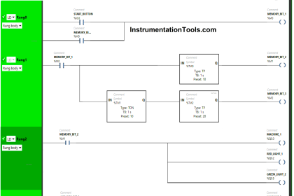
Allen Bradley PLC Logic
The engineer’s first attempt is shown here, but it contains a serious error. Identify and correct this error:

Answer :
The High pressure contact instruction should be drawn as normally-closed rather than normally-open as shown in the engineer’s first draft of the PLC program.
This particular switch signals a high-pressure condition by opening its contacts, since the real-world switch is normally-closed (NC).
We want the 3-second timer to begin timing when this switch senses a high pressure, and so we need the contact instruction to color when the real-world high-pressure switch trips (opens).
A PLC contact instruction that colors when it senses a “0” bit condition is a normally-closed (NC) instruction.
Share Your Answers
If you liked this article, then please subscribe to our YouTube Channel for PLC and SCADA video tutorials.
You can also follow us on Facebook and Twitter to receive daily updates.