As we said before PLC programming is Not Only Concerned to execute instructions that could handle the operation, No not at all.
Simplicity, reliability, and the ability to make structural adjustments to your PLC code are major factors that you have to consider when you are dealing with big projects.
Also, a major factor is the time taken by you to design the PLC code, so by the end of this article, we are going to learn a very useful programming Hint that would help you to simplify PLC coding designs using Boolean algebra and Karnaugh maps.
PLC Example for “Water Bath Heater System”
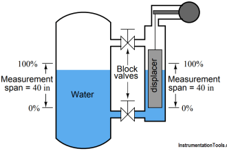
Here we have a simple Water Bath Heater (WBH) that is used to control the temperature of Natural Gas at the “Natural Gas Regulating & Metering Stations”.
There are some field instruments responsible to handle the Alarm system of the WBH such as (High Gas Pressure, High-Temperature or Low water levels… etc.).
Step1: Draw the truth table
Instead of converting the whole operation directly to a Boolean equation, it is put into a tabular form as shown in Fig. (1), and the rows and columns are chosen from the input variables.
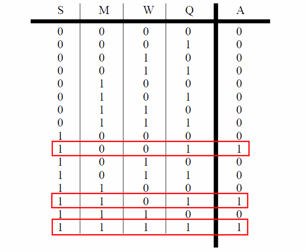
The sequence is not binary, but it is organized so that only one of the bits changes at a time, so the sequence of bits is 00, 01, 11, 10… this step is very important.
Assuming that there are four main input switches (S – M – W – Q) that they are responsible to activate the alarm system by energizing an output Horn (A).
As we could Notice in Fig. (1) the truth table of the WBH system, the output alarm would be energized just in three cases:
- S = 1 & Q = 1
- S = 1 & M = 1 & Q = 1
- S = 1 & M = 1 & W = 1 & Q = 1
NOTE:
A Truth Table is a tabular representation of all the combinations of values for inputs and their corresponding outputs. It is a mathematical table that shows all possible outcomes that would occur from all possible scenarios that are considered factual, hence the name.
Truth tables are usually used for logic problems as in Boolean algebra and electronic circuits.
Karnaugh Maps
The Karnaugh Map is defined as the graphical representation of Boolean Expressions with an array consisting of 2n cells arranged in a grid format, it will allow us to convert the WBH truth table to a simplified Boolean Expression without using Boolean Algebra calculation.
Step 2: Divide the input variables up. I choose SQ and MW
Next, the values from the truth table that are true are entered into the Karnaugh map as shown in Fig. (2).
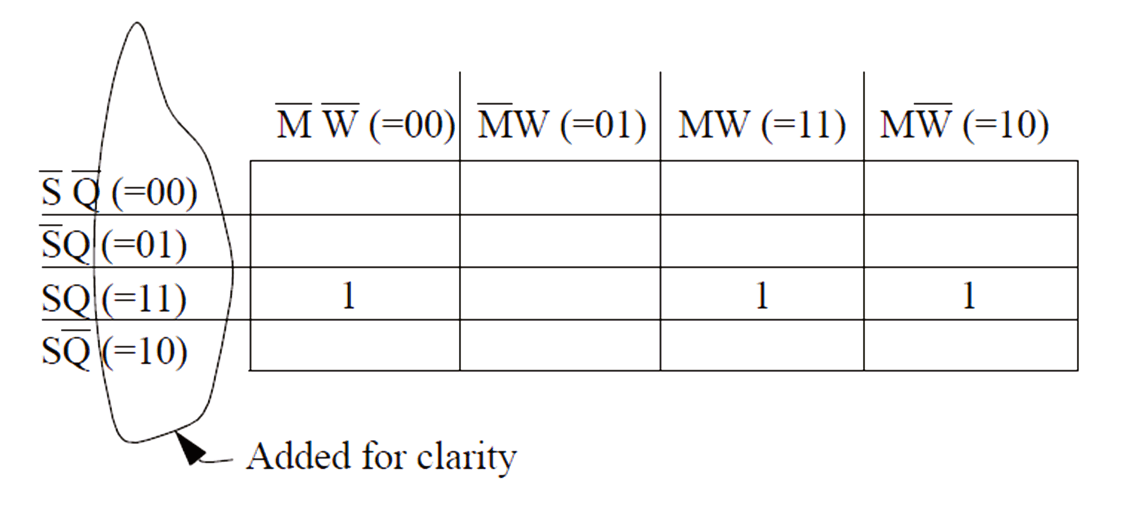
Zeros can also be entered, but are not necessary.
Step 3: Draw a Karnaugh map based on the input variables
Step 4: Look for patterns in the map
When bits have been entered into the Karnaugh map there should be some obvious patterns.
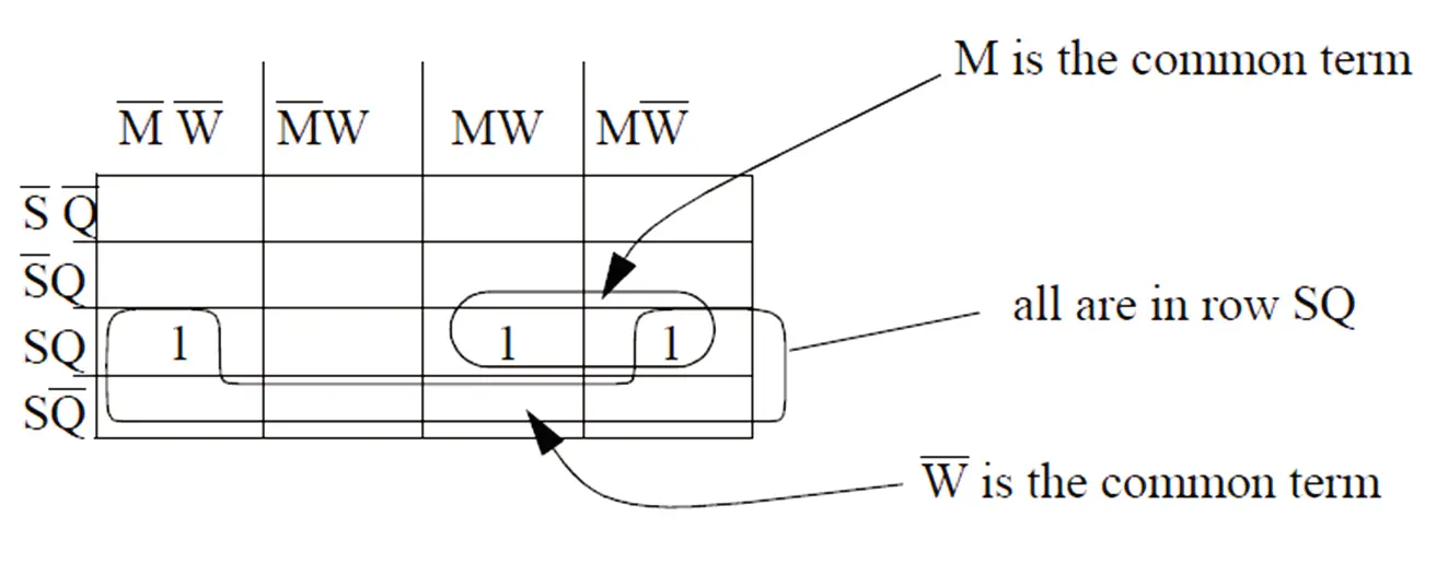
These patterns typically have some sort of symmetry. In Fig. (3) there are two patterns that have been circled.
In this case, one of the patterns is because there are two bits beside each other. The second pattern is harder to see because the bits in the left- and right-hand side columns are beside each other.
(Note: Even though the table has a left- and right-hand column, the sides, and top/bottom wrap around.)
Some of the bits are used more than once, which will lead to some redundancy in the final equation, but it will also give a simpler.
Step 5: Write the equation using the patterns
The patterns can then be converted into a Boolean equation. This is done by first observing that all of the patterns sit in the third row as shown in Fig. (3), therefore the expression will be ANDed with SQ.
Next, there are two patterns in the second row,
- One has (M) as the common term.
- The second has (W bar) as the common term.
So, either (M) OR (W bar) will be ANDed with SQ.
These can now be combined into the equation:
A = S . Q . (M + Ẇ)
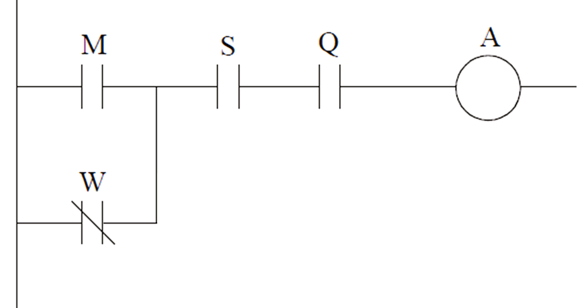
Step 6: Convert the equation into ladder logic
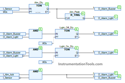
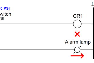
Finally, the equation is converted to ladder logic as shown in Fig. (4).
Karnaugh maps are an alternative method to simplifying equations with Boolean algebra. It is well suited to visual learners and is an excellent way to verify Boolean algebra calculations.
The example shown was for four variables, thus giving two variables for the rows and two variables for the columns. More variables can also be used. If there were five input variables there could be three variables used for the rows or columns with the pattern 000, 001, 011, 010, 110, 111, 101, 100.
If there is more than one output, a Karnaugh map is needed for each output.
Resources
- Automating Manufacturing Systems with PLCs
(Version 4.6, December 15, 2004) By/ Hugh Jack
If you liked this article, then please subscribe to our YouTube Channel for Instrumentation, Electrical, PLC, and SCADA video tutorials.
You can also follow us on Facebook and Twitter to receive daily updates.
Read Next:
- Redundancy in Siemens PLC
- Allen Bradley PLC Hardware
- Motor Classic Control Circuits
- Control System Cyber Security
- Features of Scada in IoT System