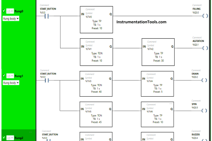
Timers are very important instructions in any PLC logic; you can hardly find any automation code that doesn’t include a timer inside. There are many types of timers you can use but in this article, we will talk about the most commonly used timers in Siemens PLC.
Contents:
- What are timers in PLCs?
- Pulse Timers TP.
- ON-Delay timers TON.
- OFF-Delay timers TOF.
- Retentive on delay timer TONR.
- Example program simulation.
- Conclusions.
What are Timers in PLC?
Timers in PLCs are built-in function blocks FBs that are used to provide the same timing instructions as a mechanical timing relay would do.
Timers are function blocks in the sense that they will need a data instance associated with them each time you use a timer. This data instance will include all data related to the operation of the timing instruction.
Timers in PLC Programming
The most commonly used timers in PLC programming are Pulse timers, on-delay timers, retentive on-delay timers, and off-delay timers.
Some PLCs might include more timers than these 4, but they will basically be some sort of a combination of the 4 basic timers.
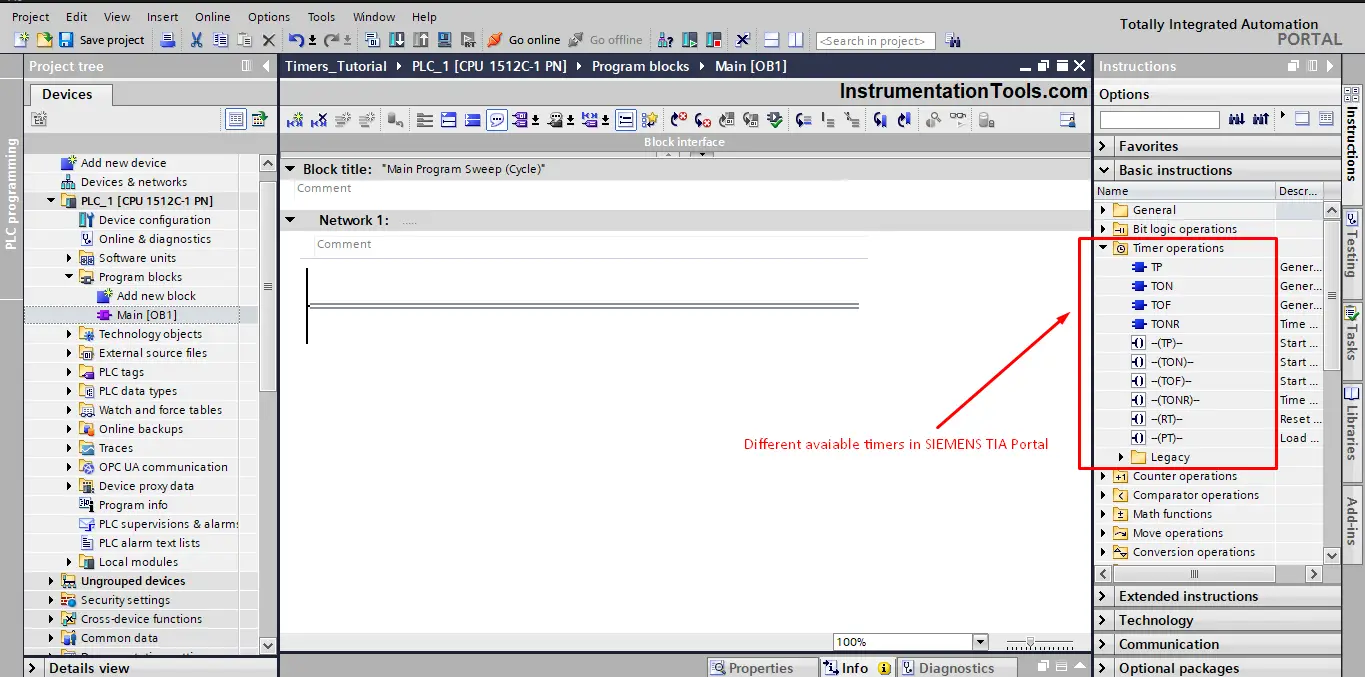
You can find the 4 timers in the Siemens TIA Portal instruction tab. See picture 1.
Pulse Timer
You can use the Pulse timer (TP) instruction to generate a pulse for a specified amount of time.
The pulse timer will set the Q output for a programmed duration when the result of the logic operation (RLO) at input IN changes from “0” to “1” (positive signal edge).
The programmed time PT begins when the instruction starts. While Output Q is set for the duration PT, the detection of a new positive signal edge at the IN input has no influence on the signal state at the Q output.
You can scan the current time value at the ET output. The timer value starts at T#0s and ends when the value of the time duration PT is reached. When the time PT has elapsed and the signal state at input IN is “0”, the ET output is reset.
The Pulse Timer instruction can be placed within or at the end of the network. It requires a preceding logic operation.
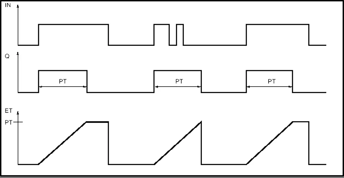
Each call of the Pulse timer instruction must be assigned to an instance data in which the timer data is stored. See picture 2 for the timing diagram of a pulse timer.
You use a pulse timer in your program by dragging and dropping the TP instruction into your network. See picture 3.
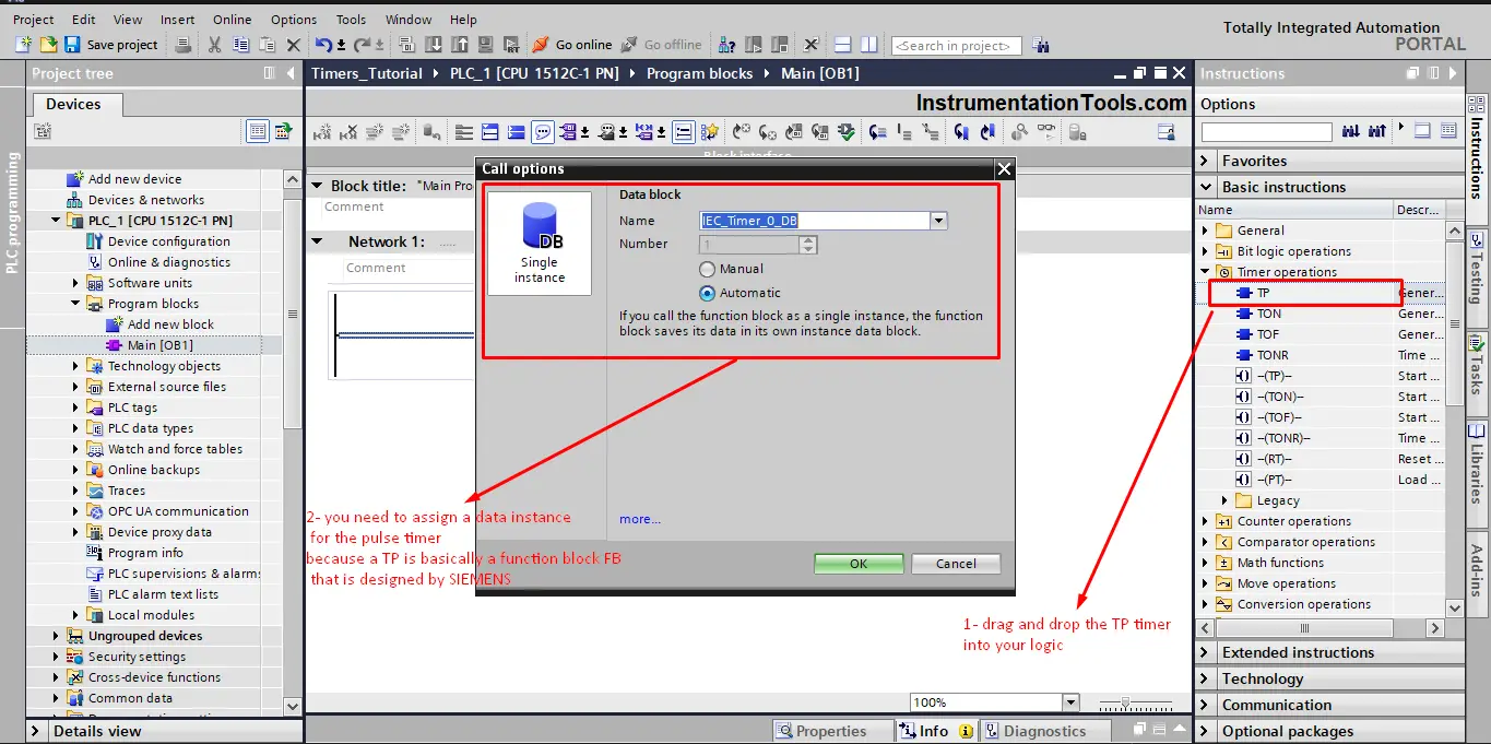
As we said before, a pulse timer is a function block FB, so when calling a pulse timer you will have to assign a data instance with the timer. As you see in the last picture.
For better understanding, we will create a simple network with the pulse timer to see how it works when running a simulation. See picture 4.
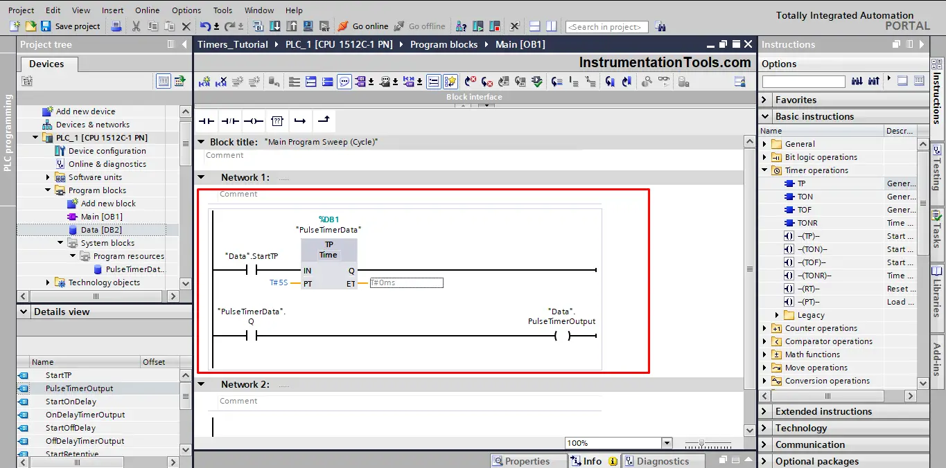
A global data block was created and inside this DB we will define some tags for our logic. A StartTP tag is used to start the pulse timer and a PulseTimerOutput tag will be true when the pulse timer is triggered.
ON-Delay Timer
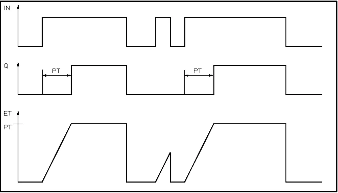
You can use the ON-Delay Timer (TON) instruction to delay the setting of the Q output by the programmed time PT. The instruction is started when the result of the logic operation (RLO) at input IN changes from “0” to “1” (positive signal edge). The programmed time PT begins when the instruction starts.
When the time PT has elapsed, the output Q will have the signal state “1”. Output Q remains set as long as the start input is still “1”. When the signal state at the start input changes from “1” to “0”, the Q output is reset.
The timer function is started again when a new positive signal edge is detected at the start input.
The TON instruction can be placed within or at the end of the network. It requires a preceding logic operation.
Each call of the ON-Delay timer instruction must be assigned to an instance data in which the timer data is stored. See picture 5 for the TON timing diagram.
You use the on-delay timer in your program by dragging and dropping the TON instruction into your network. See picture 6.
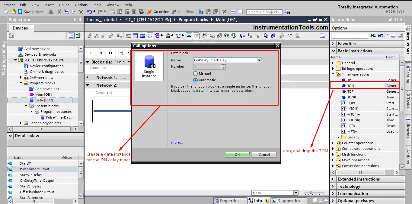
As we said before, a TON timer is a function block FB, so when calling a TON you will have to assign a data instance with the timer. As you see in the last picture.
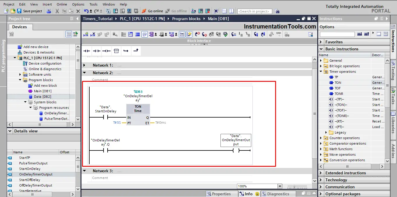
For better understanding, we will create a simple network with the ON-Delay timer to see how it works when running a PLC simulation. See picture 7.
Off-delay TIMER
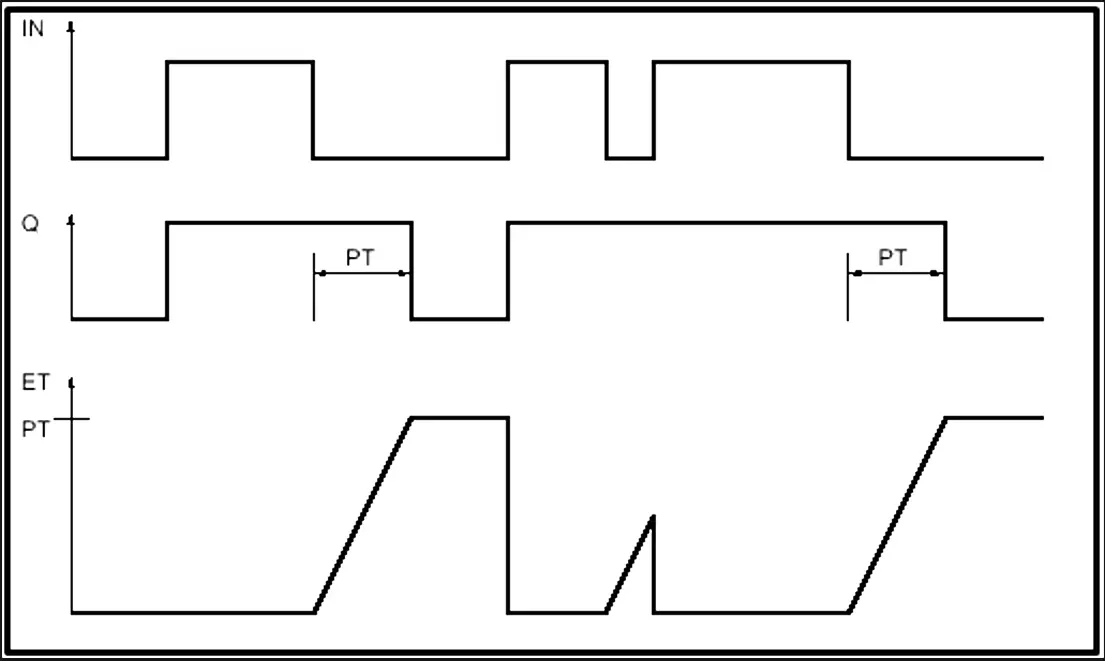
You can use the Off-delay Timer (TOF) instruction to delay resetting of the Q output by the programmed time PT.
The Q output is set when the result of the logic operation (RLO) at input IN changes from “1” to “0” (negative signal edge). When the signal state at input IN changes back to “1”, the programmed time PT starts.
The Output Q remains set as long as the time duration PT is running. When the PT time duration expires, the Q output is reset. If the signal state at input IN changes to “1” before the PT time duration expires, the timer is reset. The signal state at the output Q continues to be “1”.
The Off-delay timer instruction can be placed within or at the end of the network. It requires a preceding logic operation.
Each call of the “Generate off-delay” instruction must be assigned to a data instance in which the timer data is stored. See picture 8 for the TOF timing diagram
You use the TOF in your logic by dragging and dropping the instruction into your code as you said with the TP and TON before.
We will create a simple code with a TOF timer, so we can see how it behaves when we start the PLC simulation. See picture 9.
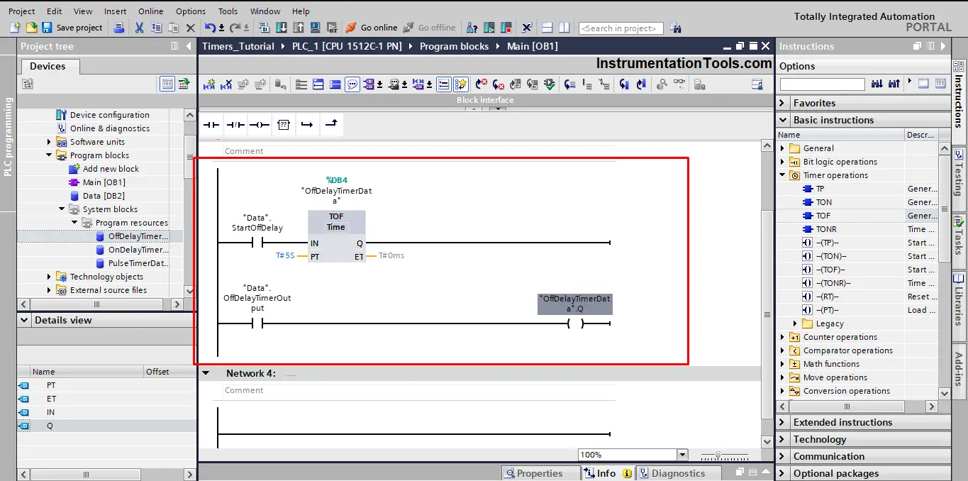
Keep in mind that the start signal StartOffDelay and the output OffDelayOutput are tags defined inside the global data block we just created.
Retentive On Delay Timer (Accumulator)
The Retentive On Delay Timer (TONR) instruction is used to accumulate time values within a period set by the parameter PT. When the signal state at the IN input changes from “0” to “1” (positive signal edge), the time measurement is executed and the time PT starts.
While the time PT is running, the time values are accumulated that are recorded when the IN input has signal state “1”.
The accumulated time is written to the ET output. When the duration PT expires, the output Q will have the signal state “1”.
The Q parameter remains set to “1”, even when the signal state at the IN parameter changes from “1” to “0” (negative signal edge).
The R input resets the ET and Q outputs regardless of the signal state of the start input.
The TONR instruction can be placed within or at the end of the network. It requires a preceding logic operation.
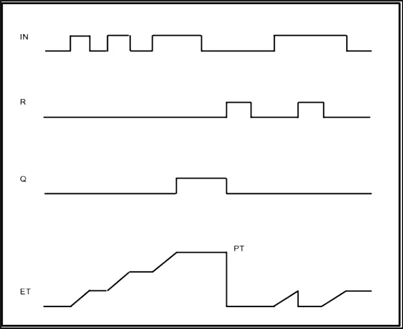
Each call of the TONR instruction must be assigned a data instance where the timer data is stored. See picture 10 for the TONR timing diagram.
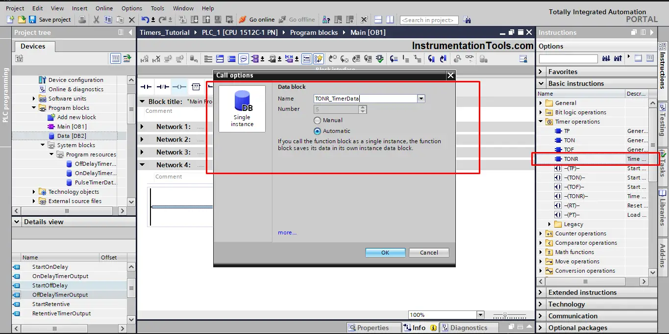
To use the TONR timer in your logic, you need to drag and drop the instruction in the coding area, you have to assign a data instance as we mentioned before. See picture 11.
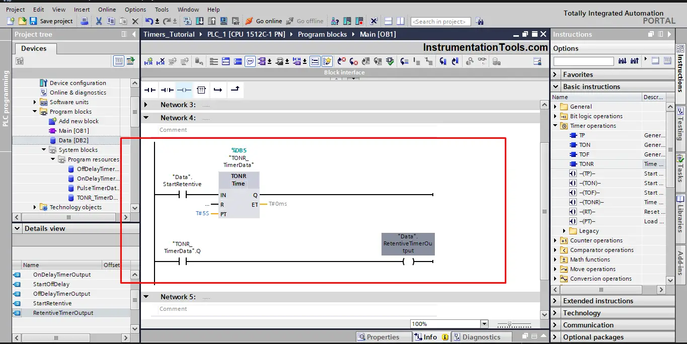
As we did with the last 3 timers, we will also create a simple logic for the TONR to see how it works in the simulation. See picture 12.
Example PLC Timer Program Simulation
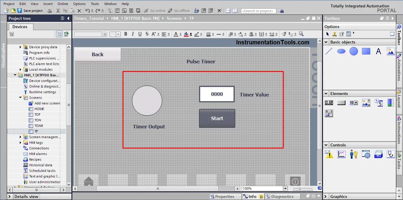
For the sake of simulation, we will create a simple HMI project.
In this project, we have created a separate screen for each type of timer, and on each HMI screen, you will find a representation of the timer similar to what you can see in the next picture. See picture 13.
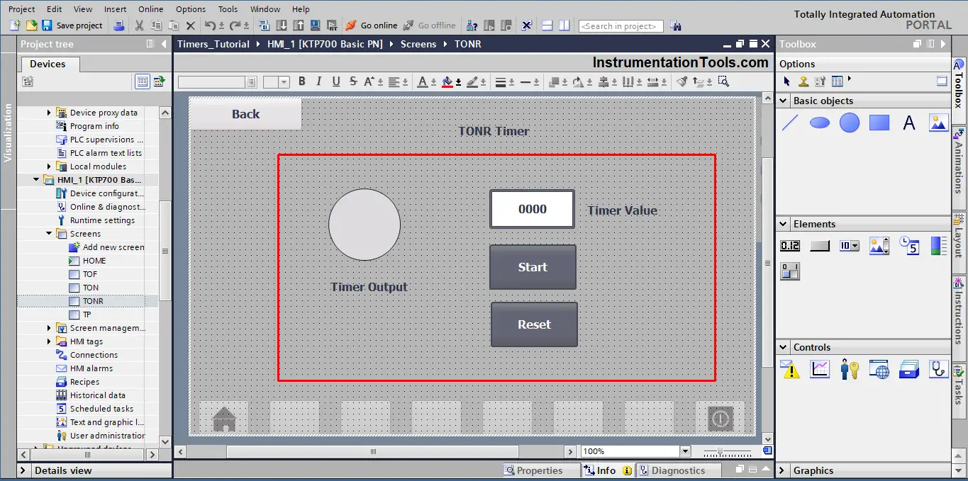
Keep in mind that the screen for TONR will have an extra Button for the Reset signal. See picture 14.
After you compile the logic code we made and run the simulation for the PLC and the HMI.
Try to experiment with the logic through the HMI screens and buttons and see if the behavior of each timer matches the explanation given above.
See the next video for the program simulation.
PLC Timer Programming Examples
Some of the example ladder logics are shared for your reference.
- Pause the Timer PLC Ladder Logic
- PLC Timer for Motor Direction Change
- Extend Timer Duration Logic in PLC
- PLC Timers Program Example Code
Conclusion
- Timers are very important tools used with any PLC logic.
- Different types of timers are available to match different requirements.
- A timer instruction is a function block, so you have to assign a data instance with it.
- A best practice when working with timers is to not make the PT time as a constant value, you should instead make this value configurable through an HMI to give the operator a wider range of control.
If you liked this article, then please subscribe to our YouTube Channel for Instrumentation, Electrical, PLC, and SCADA video tutorials.
You can also follow us on Facebook and Twitter to receive daily updates.
Read Next:
- Function Blocks in PLC
- 1oo2 Safety Logic in PLC
- Automation Project Investment
- Industrial Automation Solution
- Two Hand Press Control Circuit