In this article. you will learn the motion detection-based street light control using a sensor with PLC logic solution.
Note: This PLC logic is prepared for learning purposes. It can be used to learn ladder logic programming.
Motion Detection based Street Light
Problem Statement:
Design a PLC ladder logic for the following application.
We are using one motion detection sensor to control Street Light.
The Street Light gets ON for 20 seconds when there is any movement detected and then blinks with an interval of 2 seconds, and gets turned OFF after 30 seconds.
Note: In this example, the timings are reduced for easy learning purposes. In real-time, the timings are in hours.
PLC Logic Solution
Instrumentation Tools provides PLC logic solutions for simple and advanced programming examples.
This PLC video explains the street lights programming from scratch.
Inputs/Outputs
Digital Inputs:
Sensor: I0.0
Digital Outputs:
Street Light: Q0.0
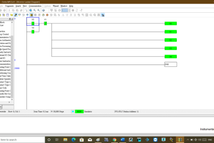
Ladder Diagram
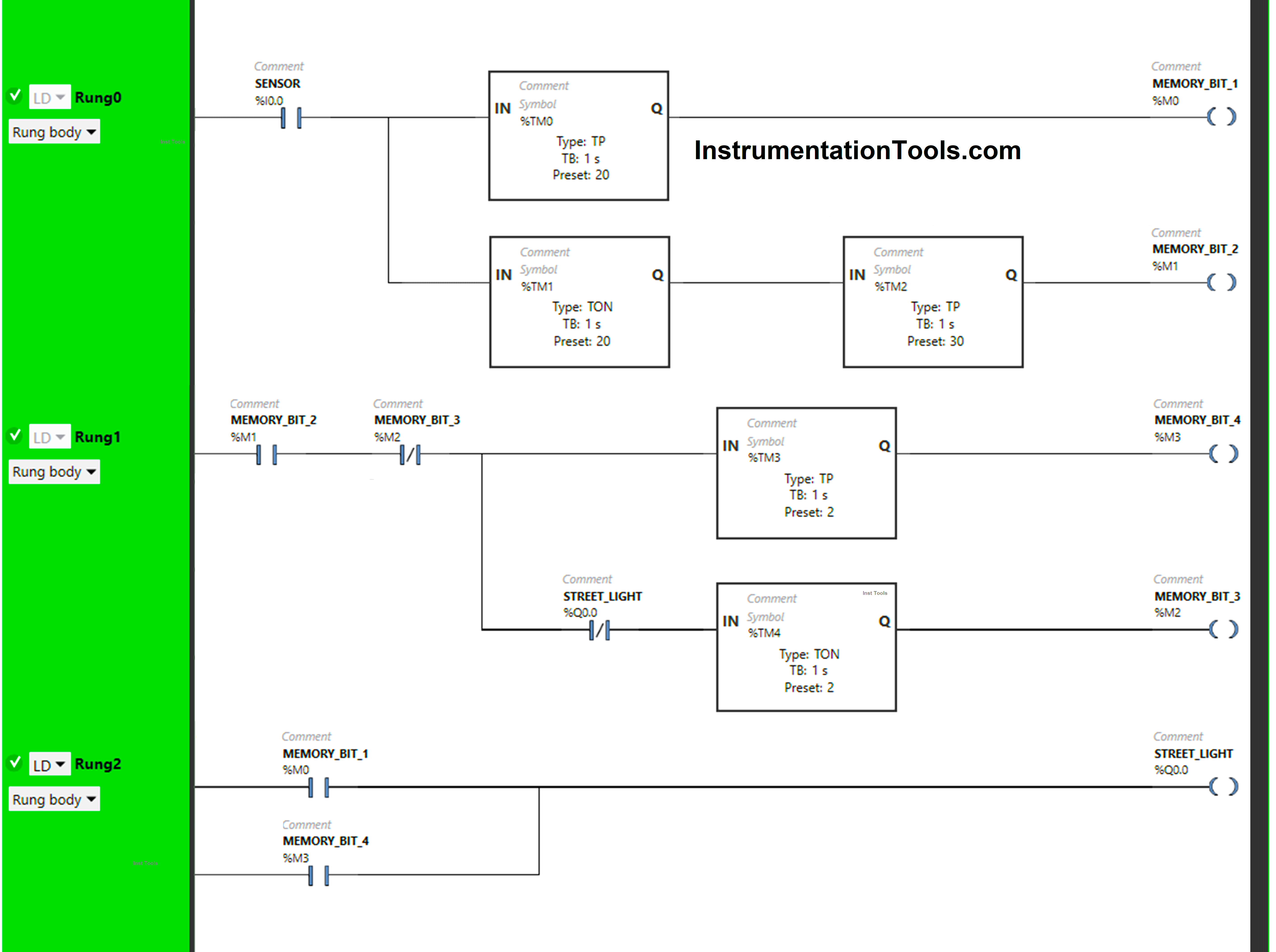
Programming Explanation
We have used Normally Open Contacts for Sensor (I0.0), Memory Bit 1 (M0), Memory Bit 2 (M1), and Memory Bit 4 (M3).
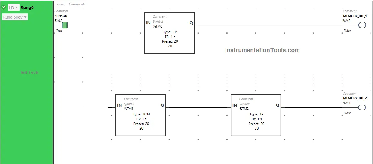
In Rung 0:
- Normally Open Contacts are used for Sensor (I0.0) to Turn ON Memory Bit 1 (M0) and Memory Bit 2 (M1).
- Timer Function Block type TP is used to Turn ON Memory Bit 1 (M0) for a limited time.
- Timer Function Block type TON is used to delay the turning ON time of Memory Bit 2 (M1) for some time.
- Timer Function Block type TP is used to Turn ON Memory Bit 2 (M1) for a limited time.
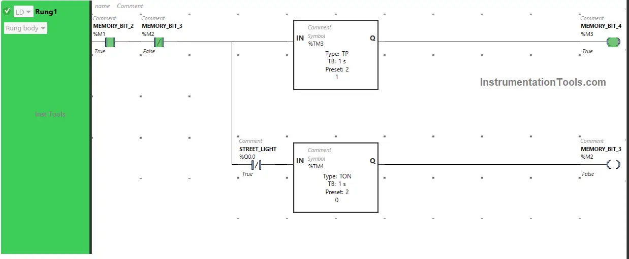
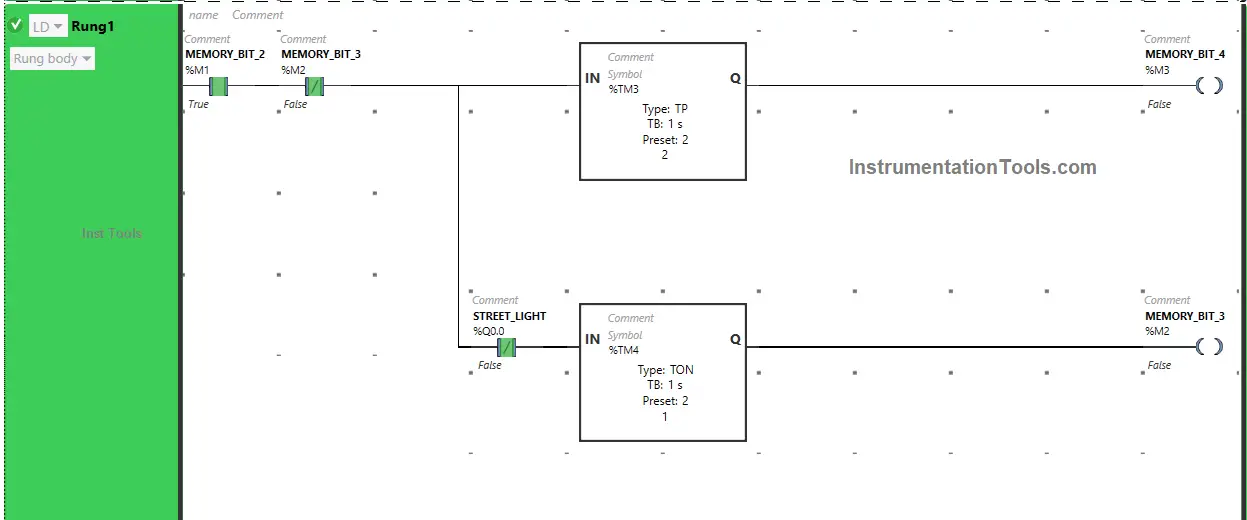
In Rung 1:
- Normally Open Contacts are used for Memory Bit 2 (M1) to Turn ON Memory Bit 4 (M3) and Memory Bit 3 (M2).
- Normally Closed Contact is used for Memory Bit 3 (M2) to turn OFF Memory Bit 4 (M3).
- Timer Function Block type TP is used to Turn ON Memory Bit 4 (M3) for a limited time.
- Normally Closed Contact is used for Street Light (Q0.0) to turn ON Memory Bit 3 (M2).
- Timer Function Block type TON is used to delay the turning ON time of Memory Bit 3 (M2) for some time.
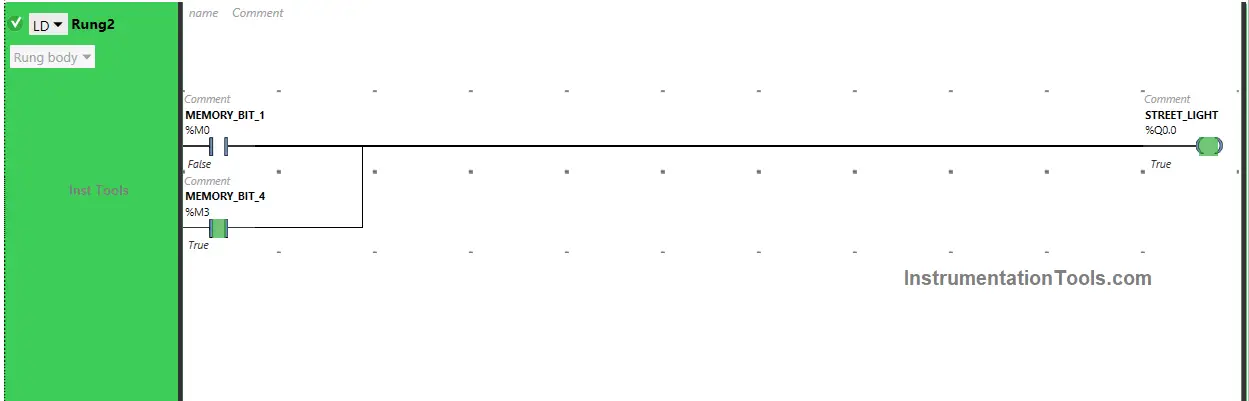
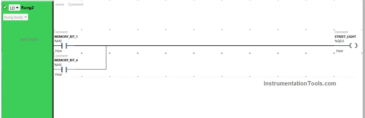
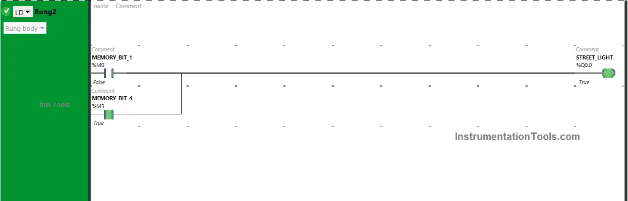
In Rung 2:
- Normally Open Contacts are used for Memory Bit 1 (M0) and Memory Bit 4 (M3) to turn ON the output Street Light (Q0.0).
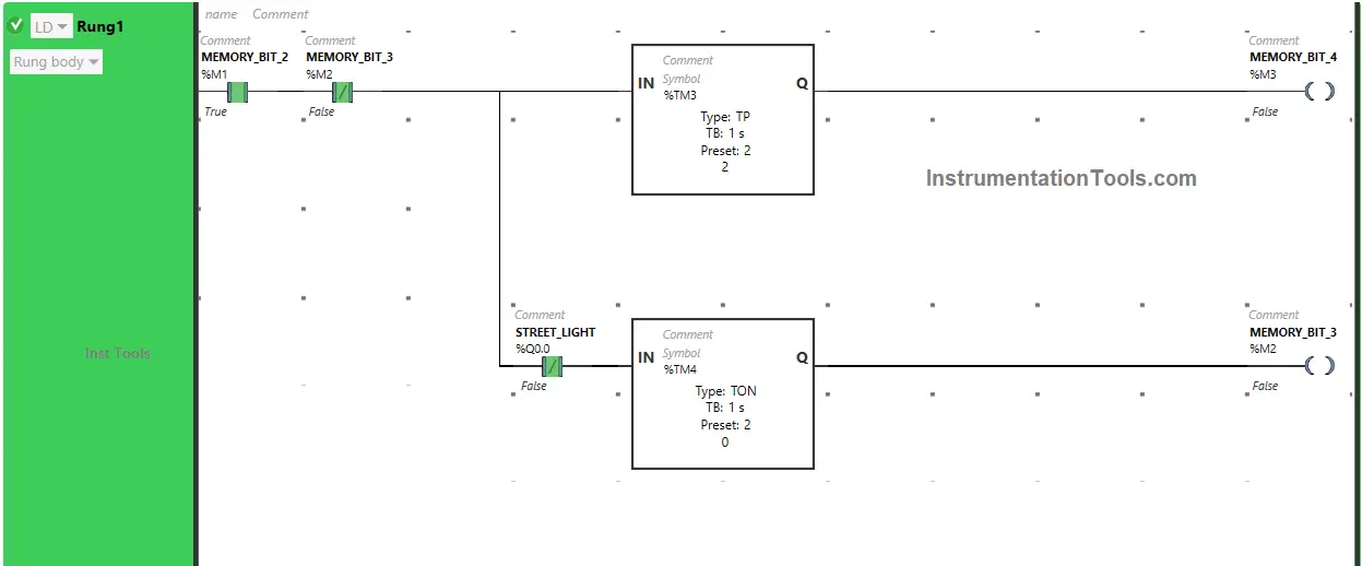
Simulation Result: When the Sensor detects movement
Now we simulate the PLC program and discuss the results. We show the partial logic with different simulation steps. We recommend you to watch the above video for detailed explanation.
When Sensor (I0.0) gets activated (Sensor detects movement), Memory Bit 1 (M0) turns ON as Normally Open Contact used for Sensor (I0.0) allows the signal to through it.
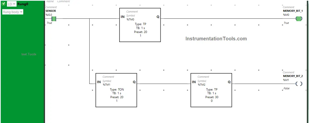
When Memory Bit 1 (M0) turns ON in Rung0, Normally Open Contact used for Memory Bit 1 (M0) will be in True state and pass the signal to turn ON the output Street Light (Q0.0) or Street Light turns ON.

In Rung0, Memory Bit 1 (M0) will turn OFF after 20 seconds as Timer Function Block type TP is used to turn ON Memory Bit 1 (M0) for a limited time. The time is set to 20 seconds.
After 20 seconds, Memory Bit 1 (M0) turns OFF.
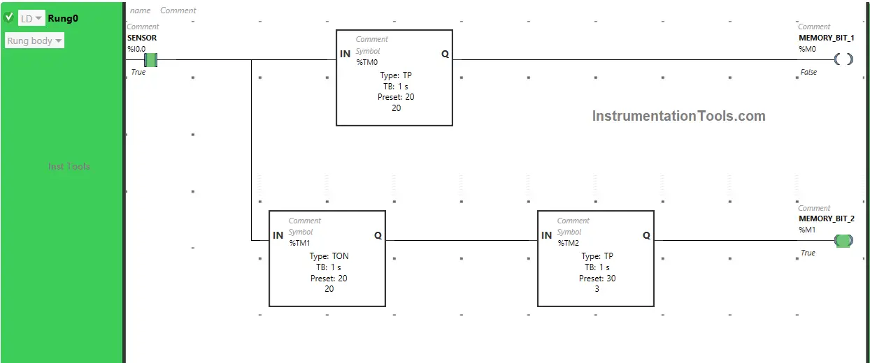
When Sensor (I0.0) gets activated (Sensor detects movement), Memory Bit 2 (M1) turns ON but after 20 seconds (i.e immediately after Memory Bit 1 (M0) turns OFF) as Timer Function Block type TON is used to delay the turning ON time of Memory Bit 2 (M1).
The time is set to 20 seconds. After 20 seconds, Memory Bit 2 (M1) will turn ON but only for a limited time as Timer Function Block Type TP is used to turn ON Memory Bit 2 (M1) for a limited time.
When Memory Bit 2 (M1) turns ON in Rung0, Normally Open Contact used for Memory Bit 2 (M1) will be in True state and pass the signal through it.
In a false state, Memory Bit 3 (M2) also passes the signal to turn ON Memory Bit 4 (M3).
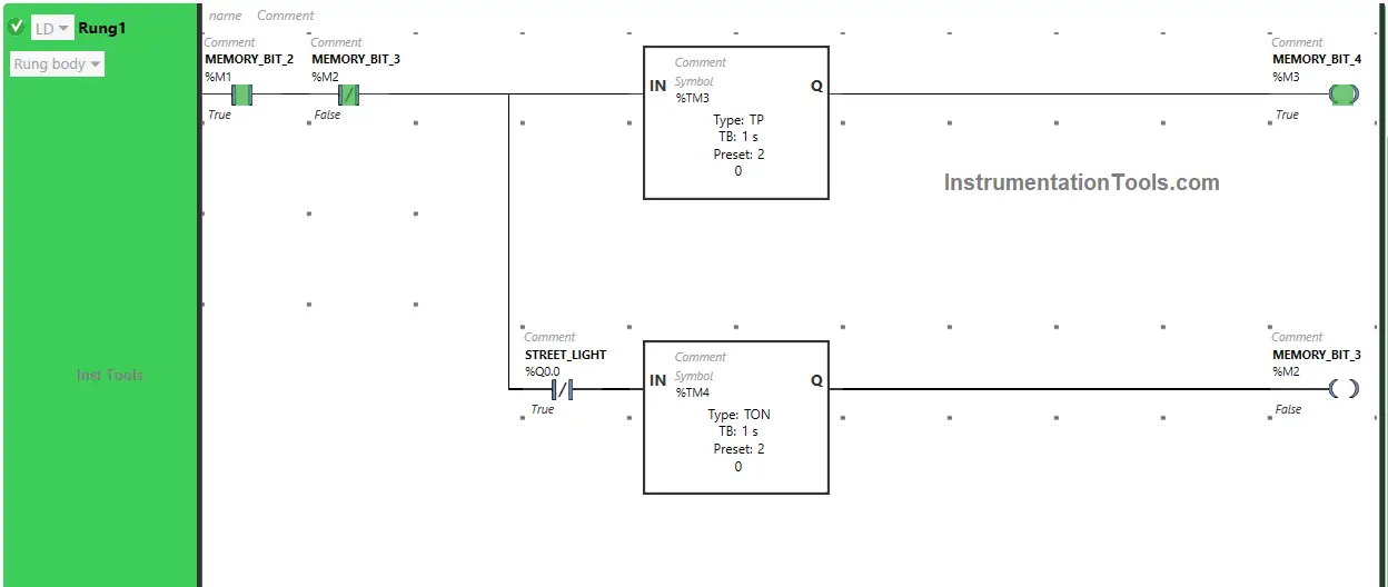
When Memory Bit 4 (M3) turns ON in Rung1, Normally Open Contact used for Memory Bit 4 (M3) will be in True state and the output Street Light (Q0.0) still remains ON.
Memory Bit 4 (M3) in Rung1 turns OFF after some time as Timer Function Block type TP is used to turn ON Memory Bit 4 (M3) for a limited time.
The time is set to 2 seconds. After 2 seconds, Memory Bit 4 (M3) turns OFF.
When Memory Bit 4 (M3) turns OFF in Rung1, Normally Open Contact used for Memory Bit 4 (M3) in Rung2 will be in a False state and the output street Light (Q0.0) turns OFF.
When the output Street Light (Q0.0) turns OFF in Rung2, Normally Closed Contact used for Street Light in Rung0 will be in a False state and passes the signal to turn ON Memory Bit 3 (M2) and Memory Bit 3 (M2) turns ON but it will turn OFF within no time because in Rung1, Normally Closed Contact is used for Memory Bit 3 (M2).
In Rung1, Normally Closed Contact used for Memory Bit 3 (M2) will also turn ON and OFF within no time and the whole process in Rung1 and Rung2 will restart and will run in a loop till the Timer Function Block type TP used for Memory Bit 2 (M1) in Rung0 will reach its time limit.
The time is set to 30 seconds. After 30 seconds, Memory Bit 2 (M1) will turn OFF. When Memory Bit 2 (M1) turns OFF in Rung0, Normally Open Contact used for Memory Bit 2 (M1) will be in a False state and does not allow the signal to pass through it and the whole process stops.
Advanced Street Lights PLC Program
This video explains the advanced Street Lights PLC programming concept. The video explains the project objective, PLC wiring, logic brief, and PLC programming with HMI design and simulation.
If you liked this article, please subscribe to our YouTube Channel for PLC and SCADA video tutorials.
You can also follow us on Facebook and Twitter to receive daily updates.
Read Next:
- PLC Programming for Motor Feedback Fail Logic
- PLC Example Programming using LogixPro Simulator
- Ladder Logic Program for Push Button and Motor
- PLC Programming Multi-Motor Control Ladder Logic
- Conveyor Operation with a Backup Motor using PLC