A limit switch is an electromechanical unit that consists of an actuator that is connected mechanically to the set of contacts.
When the object travels towards and comes in touch with the actuator, the limit switch performs the contacts to make or break an electrical connection.
Limit Switch
Mechanical limit switches consist of a mounted actuator arm that operates a set of electrical contacts when the arm is dislocated.
Limit switch failures are generally mechanical in nature.
Principle:
Automatic operation of a machine requires the use of limit switches that can be activated by the motion of the machine. A limit switch is used to convert this mechanical motion of the machine to an electrical signal to switch circuits.
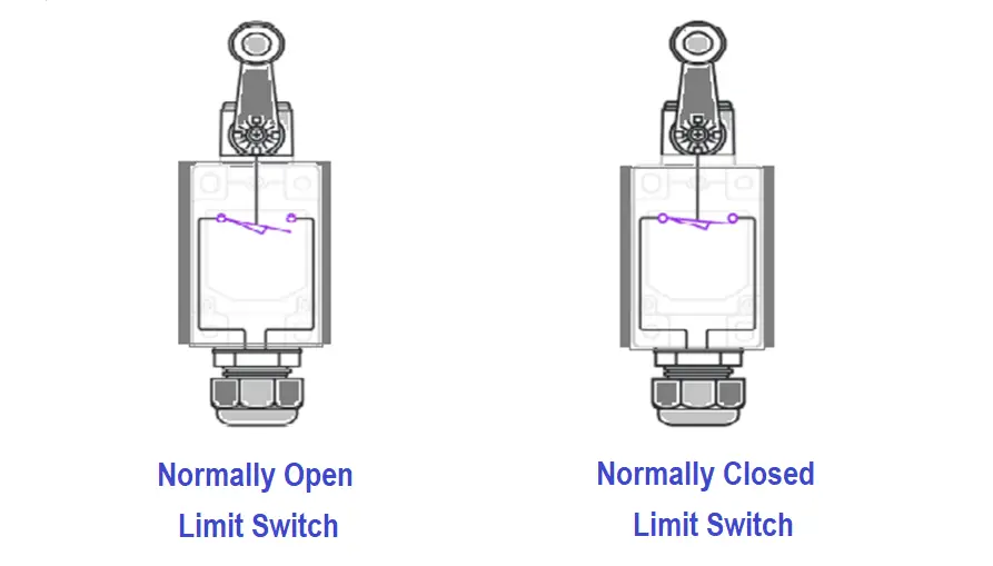
The operating position of the limit switch is where the limit switch changes from its normal (NO or NC) to its operating state. The release position is where the contact change from their operating state to their normal state.
Types of Mechanical limit switches
- Lever-type limit switch
- Push type limit switch
Lever Type Limit Switch
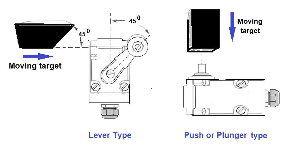
In the case of the lever type limit switch, the actuating arm is a rod connected to a lever shaft which is free to rotate when the rod is dislocated.
When the forces displaying rod are removed, the lever shaft is returned to its normal state by a return spring.
The lever shaft has a roller mounted on its bottom, which rotates a rocker as it changes its position from right side to left side.
The mechanical action operates one are more contacts which are mounted on the other side of the limit switch as shown in the above figure.
The electrical contact may be open or close initially. The action of the actuator and lever arms takes it from one state to the other state. Hence normally open limit switch will be closed and when activated and the closed switch will be open when actuated.
Push Type Limit Switch
In the push type limit switch in the above figure, the contact gets operated from the depression of the contact lever arm.
Based on the type of motion, limit switches are classified as
- Rotary motion
- Linear motion
Rotary Motion Limit Switch
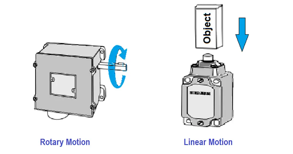
It is operated by rotating a shaft. Once the shaft reaches a set number of rotations or sets angle the switch gets activated.
Rotary limit switches are preferred where the adjustment of limits of travel is required frequently.
An important application is in overhead cranes for hoisting and lowering motion.
Linear Motion Limit Switch
It detects and contact changes are triggered by linear motion.
In this case the once the limit switch is fixed, only very little adjustment is possible by adjusting the lever position.
Limit Switches are used for
- Momentary contact
- Maintained contact
Momentary Contact
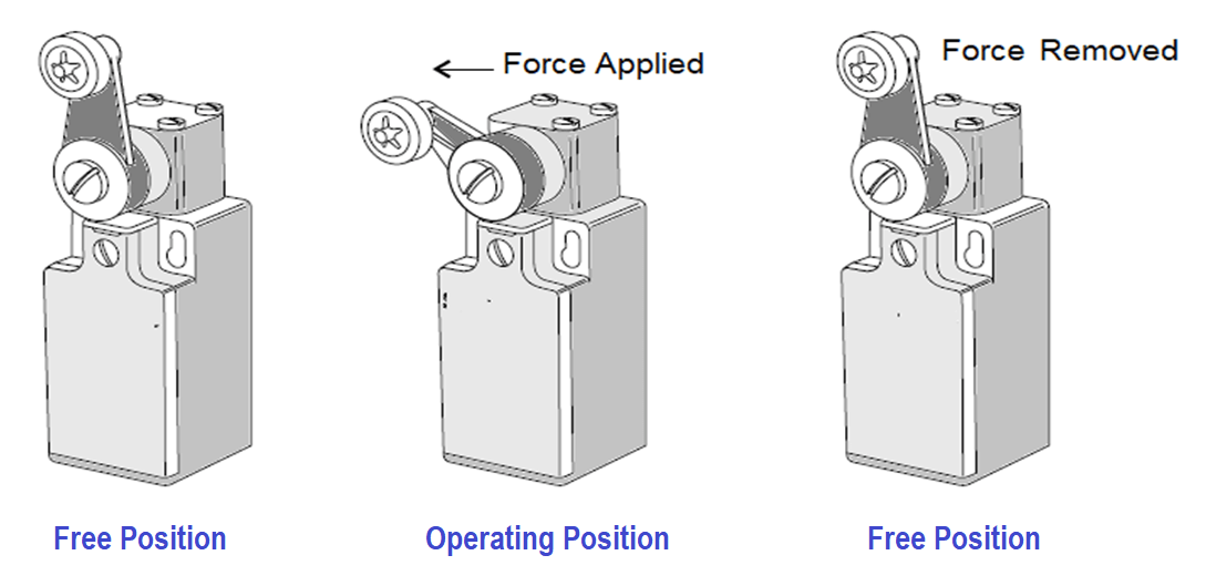
Image Courtesy: Siemens
When the target comes in contact with the actuator arm, it makes to move the actuator from the free position to the operating position.
At this point, the electrical contacts also change the state. When the target moves away, the actuating arm and also the contacts become normal.
Maintained Contact
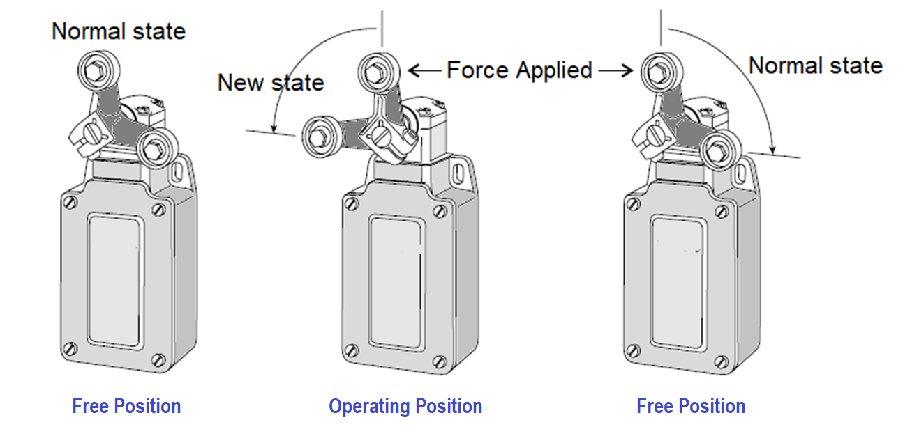
Image Courtesy: Siemens
In some applications, there is a need to remain actuator and contacts in the same state even after the target moved away. Need to apply a force to bring back the actuator to a normal state.
Advantages
- High current capability
- Low cost
- Familiar with low technological sensing.
Disadvantages
- Wear and tear
- Requires physical contact with the target.
- Chances of contact bounce
- The response is slow compared with non-contact sensors such as proximity sensors.
Applications
- Plant automation or machinery Interlocking applications.
- Limit switches are often used in machine tools to limit the travel of a machine axis.
- Used in materials handling applications, to indicate the passage of material from one platform to another.
- Used in overhead cranes.
- Used in control panels to control the lighting.
If you liked this article, then please subscribe to our YouTube Channel for PLC and SCADA video tutorials.
You can also follow us on Facebook and Twitter to receive daily updates.
Read Next:


I appreciate so much for the information you deliver . I have really learnt more of instrumentation tools.
Please check if it is correct the following expressions;
a limit switch for right sided limit
a limit switch for left sided limit
a limit switch for up sided limit
a limit switch for down sided limit