In this article, you will learn the STAR DELTA programming using PLC controller to start or stop the induction motor (starter function).
Star–Delta Method: Three-Phase Induction Motor
Star Delta connection is a popular method for the Starting of a 3-phase induction motor. The 3-phase induction motor has 6 terminals, the Star (Y) connection is used during the motor starting time and when the motor reaches about 80% speed, the Delta (Δ) connection is converted into a Delta (Δ) connection.
At the time of the Star connection, all Phase voltages are lowered by 1/3 of 57.7% of the source voltage, and the current is reduced by about 1/3. The three-phase induction motor benefits from the Star-Delta connection that, the Star connection results in a lower current compared to the Delta connection during the startup of a motor. This helps in reducing the initial motor surge current which can be as high as 7 times the nominal current.
How the Star-Delta Program Works Using PLC?
This Star-Delta PLC program requires 4 Digital Input contacts (START, STOP, EMERGENCY, OVERLOAD), 3 Digital Output contacts (Contactor MAIN, Contactor STAR, Contactor DELTA), 4 Memory Bit allocations (Internal Relay Main, Internal Relay STAR, Internal Relay Delta, Internal Relay Timer), 1-word memory allocation (%MW0), and 1 Timer.
When the START (%I0.0) button is pressed, the system activates and activates Main Relay Internal Bit Memory (%M0) along with STAR Internal Relay Bit Memory (%M1). The timer will start counting along with the active Internal Relay contact MAIN (%M0).
The timer activated a while ago will trigger the Internal Relay Delta (%M2). Internal Relay Delta (%M2) that has been activated will turn off the signal flow flowing to the Internal Relay Main (%M0) and Timer using the Interlock function.
Please note that in EcoStruxure Machine-Basic (Schneider) software Timer Instruction requires additional Bit Memory which functions as an auxiliary contact, therefore the program added Bit Memory with the name Internal Relay Timer (%M3).
Internal Relay Main Bit Memory (%M0), Internal Relay STAR (%M1), and Internal Relay Delta (%M2) will enable Digital Output Contactor MAIN (Q0.0), Contactor STAR (Q0.1), Contactor DELTA (Q0.2) using contact NO (Normally Open).
In this PLC program, the value of the Preset Timer can also be set using MOV data instruction to move the data value from Word Memory (%MW0) to the address of the Preset Timer (%TIM0. P).
This Star Delta System program can stop if the STOP button is activated, the Emergency button is activated, and the Overload contact is active.
Addressing in PLC Program
Addressing Inputs, Outputs, TIM, Bit Memory, and Word Memory are shown below.
| Comment | Input (I) | Output (Q) | Bit Memory | Word Memory | TIMERS |
| PB_START | %I0.0 | ||||
| PB_STOP | %I0.1 | ||||
| EMERGENCY | %I0.2 | ||||
| OVERLOAD | %I0.3 | ||||
| MAIN | %Q0.0 | ||||
| STAR | %Q0.1 | ||||
| DELTA | %Q0.2 | ||||
| IR_MAIN (%M0) | %M0 | ||||
| IR_STAR (%M1) | %M1 | ||||
| IR_DELTA (%M2) | %M2 | ||||
| IR_TIMER (%M3) | %M3 | ||||
| PRESET_TIMER | %MW0 | ||||
| TIMER 0 | %TM0 |
STAR DELTA Programming
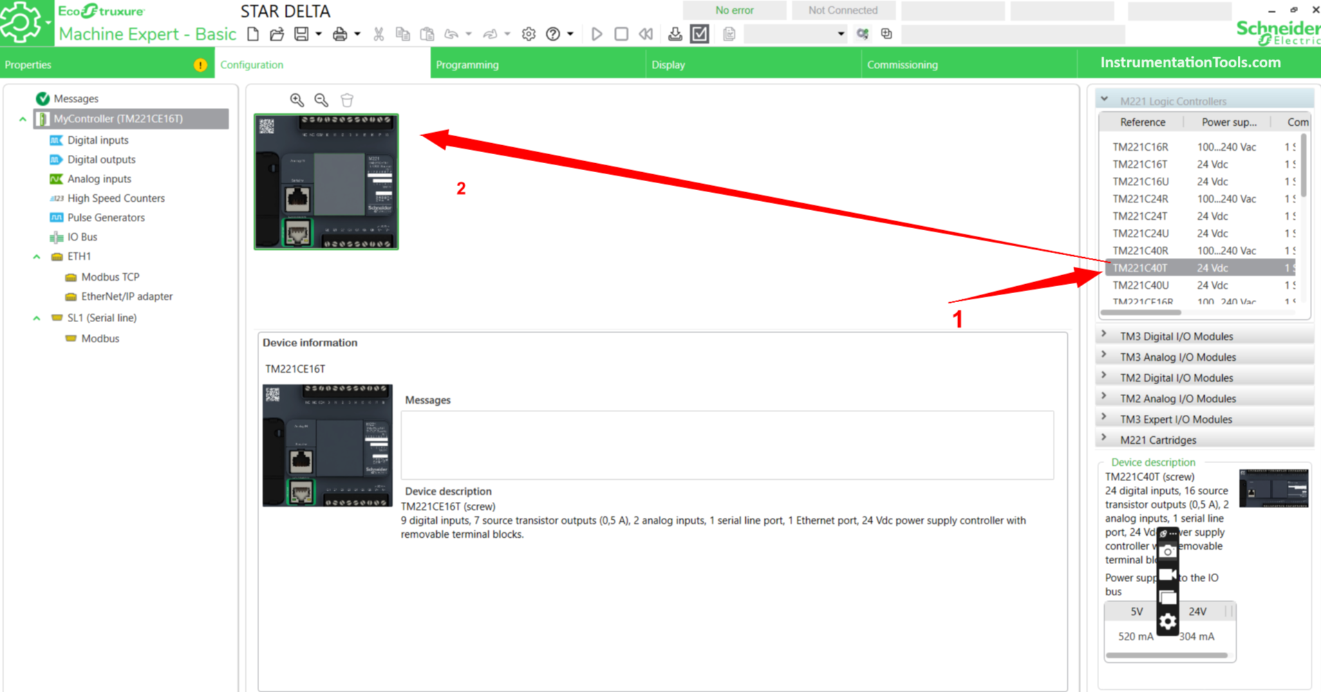
Open EcoStruxure Machine-Basic PLC Software. Enter the Configuration menu to set the type of PLC used, and Digital Input / Output contact settings to be used.
Choose PLC type, PLC as needed, in this program, I use type TM221C40T. To change or add PLC we can click the type of PLC in the list column and then drag it to the work page as shown below.
Initial Setup
Set Up Digital Input Contacts
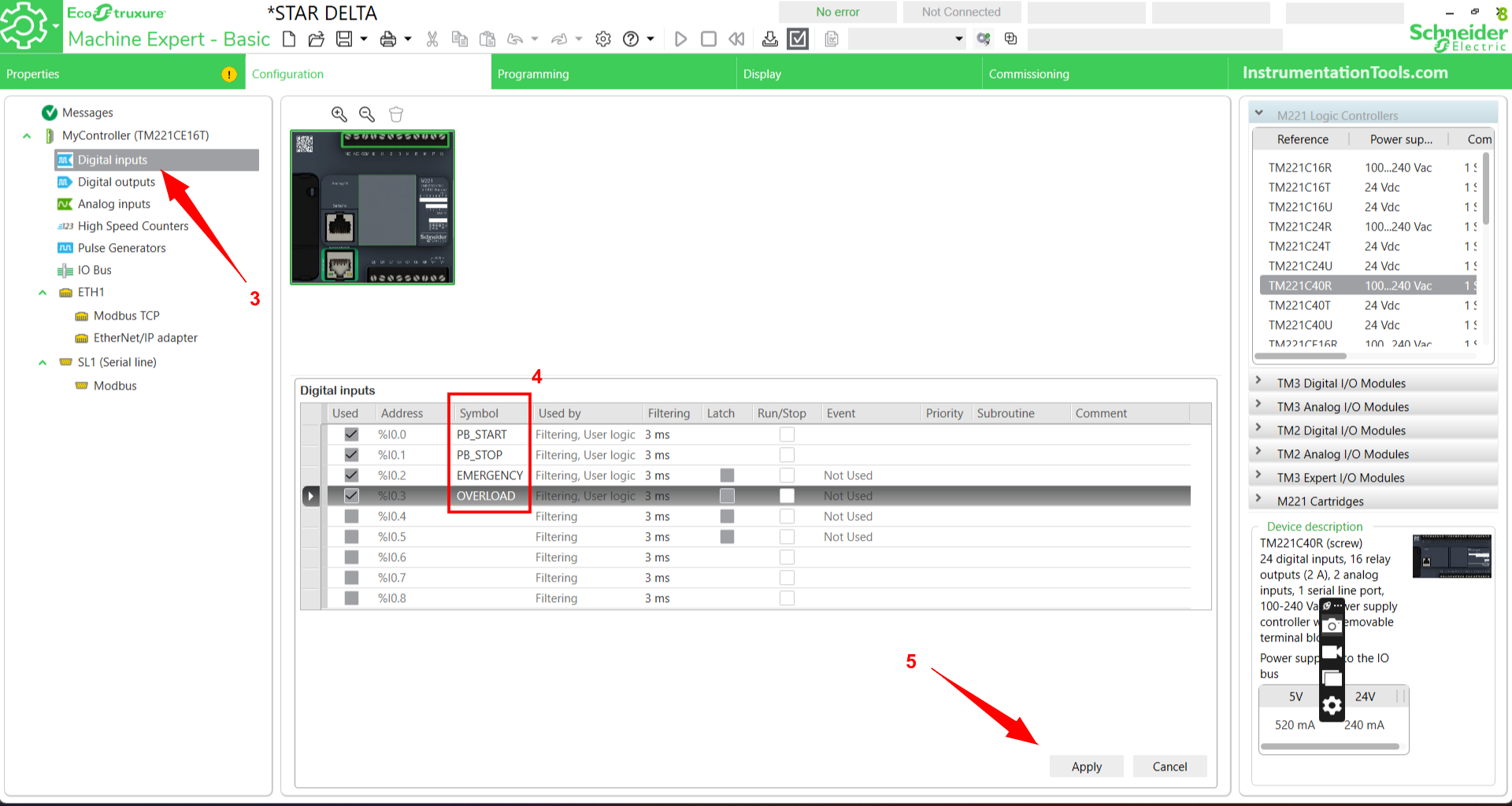
To set the Digital Input contact parameters, we have to press the Digital Input sub-menu first, then a list of Digital Input contact address parameters will appear on the work page as shown below.
Select the number of contacts to use, then name the SYMBOL column (as shown in arrow no.4). This program uses 4 Digital Inputs with names/labels PB_START(I0.0), PB_STOP(I0.1), EMERGENCY(I0.2), and OVERLOAD(I0.2).
When finished, click the “Apply” button to apply the settings that have been done. In PLC Software, the Digital Input address uses the format %I0.0 – %I0.xxx.
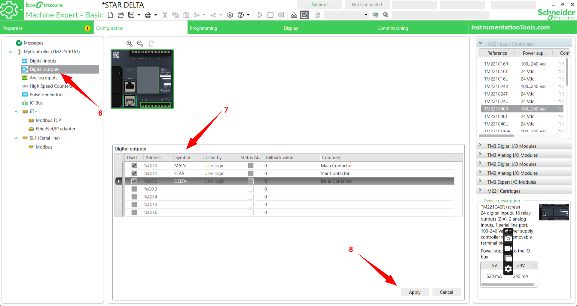
Set Up Digital Contact Outputs
Just like the method in setting Digital Input, we need to click the Digital Output Sub menu then a list of Digital Output parameters will appear on the work page.
Give a name/label to the SYMBOL column, in this program using 3 Digital Output contacts with the name/label MAIN(Q0.0), STAR(Q0.1), DELTA(Q0.2).
We can also add a description of each address to the comment column. When finished, click the “Apply” button to apply the settings that have been done.
In PLC Software, the Digital address output address uses the format %Q0.0 – %Q0.xxx.
The next step is to enter the Programming Sub menu to create a Program.
Logic Explanation
Create a Program as follows.
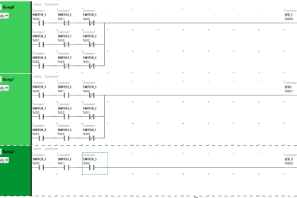
NETWORK 0
In this rung, there is 1 contact NO (Normally Open) Digital Input with label PB_START(%I0.0), 3 contacts NC (Normally Close) with label PB_STOP (%I0.1), EMERGENCY (%I0.2), and OVERLOAD (%I0.3).
Then there is a Coil labeled Bit Memory IR_MAIN( %M0) and auxiliary contacts NO (Normally Open) from IR_MAIN (%M0) which functions as Latching.
If PB_START (%I0.0) is pressed, it will send the signal to IR_MAIN ( %M0) and if PB_START (%I0.0) is released then IR_MAIN (%M0) will remain active because the Latching function.
The IR_MAIN (%M0) coil will only turn off if the NC (Normally Close) contacts of PB_STOP (%I0.1), EMERGENCY (%I0.2), and OVERLOAD (%I0.3) are active.
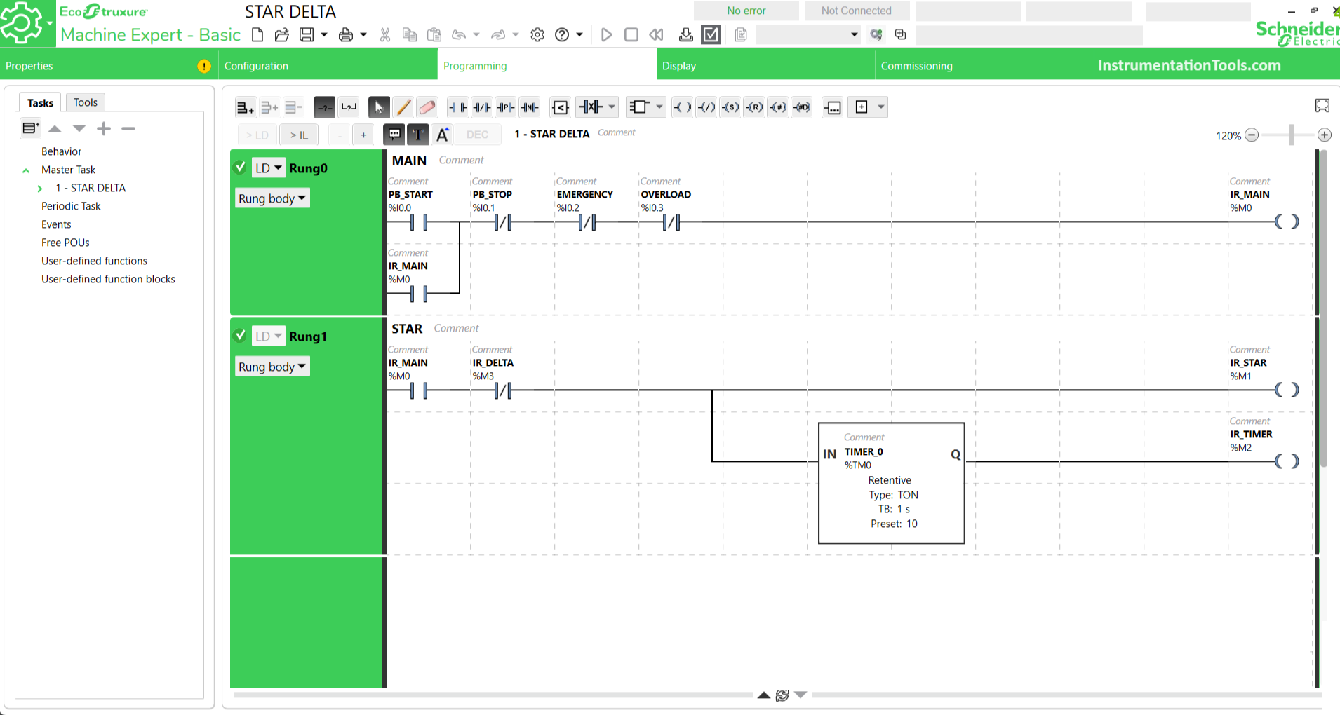
NETWORK 1
On Rung 1, if the NO (Normally Open) IR_MAIN (%M0) contact is active, it will send the signal to the Coil IR_STAR ( %M1), and at the same time it will send the signal to TIMER_0 (%TM0).
The timer will start counting until it reaches the set value/Preset. If TIMER_0 (%TM0) has reached the Preset value it will send the signal to the Coil IR_TMER (%M3).
In this rung, the system will only stop if the contact NC (Normally Close) IR_DELTA (%M2) is active and the contact NO(Normally open) IR_MAIN (%M0) is off.
Please note that the Timer used is a type of ON DELAY (TON) Retention Timer, so the Timer will start to activate if the Preset value has been reached.
If the timer Preset has not been reached but the system is turned off, the Timer will save the last calculation data and will resume the calculation if the system is active again, unless the Preset data is changed.
NETWORK 2
In Rung 2, this is a condition where the system has switched to the DELTA state. When the NO (Normally Open) contact of IR_TIMER (%M3) is active even for a moment it will trigger the Coil IR_DELTA (%M2).
Coil IR_DELTA (%M2) will remain active even though the contact NO (Normally Open) IR_TIMER (%M3) is off, this is due to the latching function of the Coil IR_DELTA (%M2).
The IR_DELTA (%M2) coil will only turn OFF if the NO (Normally Open) contact of the IR_MAIN (%M0) is OFF.
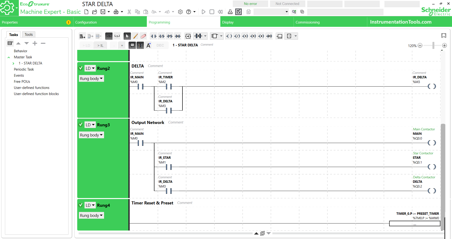
NETWORK 3
Rung 3 is a Rung that is devoted to Digital Output addresses. We can see there are 3 Coils with Digital Output addresses with names/labels MAIN (Q0.0), STAR (Q0.1), and DELTA (Q0.2).
The MAIN (Q0.0) coil will activate when the NO (Normally Open) IR_MAIN (%M0) contact is active. The STAR (Q0.1) coil will be active at the same time as the MAIN (Q0.0) coil but with the permission of the NO (Normally Open) IR_STAR (%M1) contact.
The STAR (Q0.1) coil will only be active for a moment, as long as the timer starts counting and will turn off if the Preset Timer value is reached.
The DELTA (Q0.2) coil will activate when the NO (Normally open) IR_DELTA (%M2) contact is active, and IR_DELTA (%M2) will be active when the Preset Timer has been reached.
All coils will turn off if the NO (Normally Open) contact IR_MAIN (%M0) is off.
NETWORK 4
Rung 4 functions as a timer of the TIMER_0 (%TM0) Preset by moving data from the %MW0 Word Memory allocation to the TIMER_0 (%TM0) Preset address of %TM0.P.
References
- The working system of the Star Delta control circuit on the 3-phase motor. Faiz Addawami, Ananda Yhuto Wibisono Putra.
If you liked this article, please subscribe to our YouTube Channel for PLC and SCADA video tutorials.
You can also follow us on Facebook and Twitter to receive daily updates.
Read Next:
- Basics of Star and Delta connections
- How to Blink Lights in PLC Ladder Logic?
- Electrical Ladder Diagram Control with Timers
- PLC Control a Pump based on Level Sensors
- PLC Speed Control of Induction Motor using Logic