PLC programming took a history and reference from electrical drawings. As time passed and it became difficult to troubleshoot electrical systems involving automation, a need was required for some controller to execute a logic and do the needful. This gave birth to PLC systems.
As you know, PLC programming has many types of languages and the original one is the ladder language. It should be known that electrical diagrams also help to convert it into ladder logic. In this post, we will see how to convert an electrical diagram into a PLC program.
Understand Electrical Diagram
First of all, you need to understand the electrical diagram. Refer to the below image. Every circuit has two ends – positive and negative. Current starts from the positive end and flows through the negative end.
In between, electrical components and devices come. If you refer to the image below, there are four components – the start push button, the stop push button, the auxiliary contact of the lamp, and the lamp.
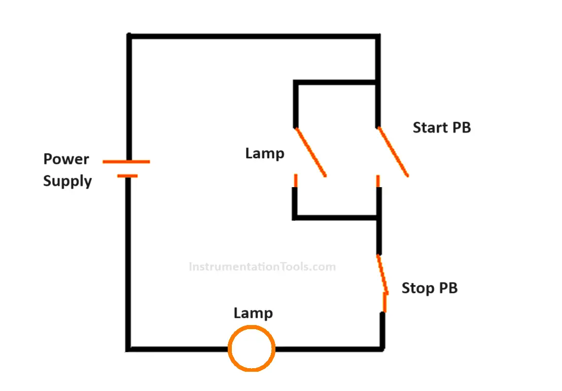
The power supply starts from the positive end and goes to the input of the start push button (NO contact). The output of the start push button goes to the input of the stop push button (NC contact). The output of the stop push button goes to the input of the lamp.
The output of the lamp is connected to the negative end supply. In parallel to the start push button, another wire goes down from the input of the button to an auxiliary contact of the lamp. The output of this contact is connected back to the output of the push button.
When the power supply is given and if the start button is pressed, the lamp will turn on as it gets the path for current. Now, if the button is released, then the lamp will turn off as it does not get the path.
So, to latch it, we therefore place the lamp contact in parallel which will hold the power supply path. When the stop button is pressed, the electrical supply path is cut off and the lamp goes off.
Converting the wiring diagram to the PLC program
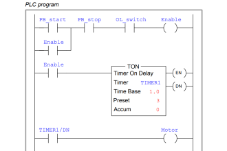
Now, once you have understood the wiring diagram, start interpreting it in the same way for PLC programming. Refer to the below image.
The ladder logic will have two power ends – left and right. Left is the equivalent to a positive power end and right is the equivalent to a negative power end.
You will need four PLC programming components – start push button -> NO contact, stop push button -> NC contact, lamp -> output coil, and lamp NO contact.
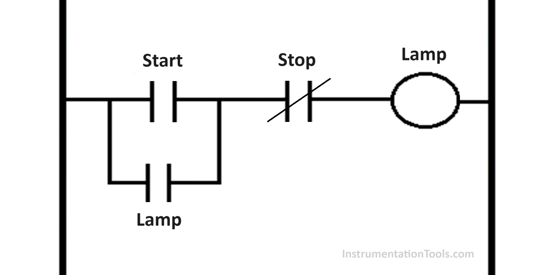
First, place the start push button NO contact. In parallel to it, place the lamp in NO contact. After this, place the stop push button NC contact. In the end, place the lamp in NO contact.
The working will be the same as discussed for the wiring diagram. You saw that the same electrical drawing was interpreted and converted into ladder logic.
The general tips to follow are:
- Understand the wiring diagram from input power to the output power. In between, see which components are placed where and how they are wired.
- In the wiring, identify the input parts and the output parts and mark them with separate colors.
- Start programming by following the diagram and placing the components in the same way as wiring is done.
- Run the program and see how it is working.
If you liked this article, then please subscribe to our YouTube Channel for Instrumentation, Electrical, PLC, and SCADA video tutorials.
You can also follow us on Facebook and Twitter to receive daily updates.
Read Next:
- Free Schneider PLC Training
- Simulation of Studio 5000
- Transferring Data Across PLC Systems
- Import GSD files into the TIA Portal
- How to Automatically Close Pop-up?