In previous articles, we talked about safety PLCs, and we showed how to use some of the most commonly used safety instructions that are built into the safety PLC, such as ESTOP instruction, SFDOOR, and Two_Hand_EN.
But what if you need to perform a certain safety functionality that is not necessarily available as a built-in function? That is not a problem. We can just use basic instructions like AND, OR, COMPARE, and TIMERS.
To create whatever safety function you want to achieve. In this article, we will learn the Safety PLC best practice tips and guidelines you can follow when programming a safety PLC function to ensure your code complies with safety standards.
Contents:
- Programming a safety PLC.
- Recommendations for Hardware Configurations.
- Recommendation for software programming.
- Conclusions.
Programming a Safety PLC
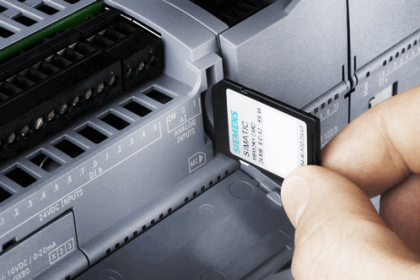
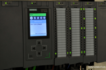
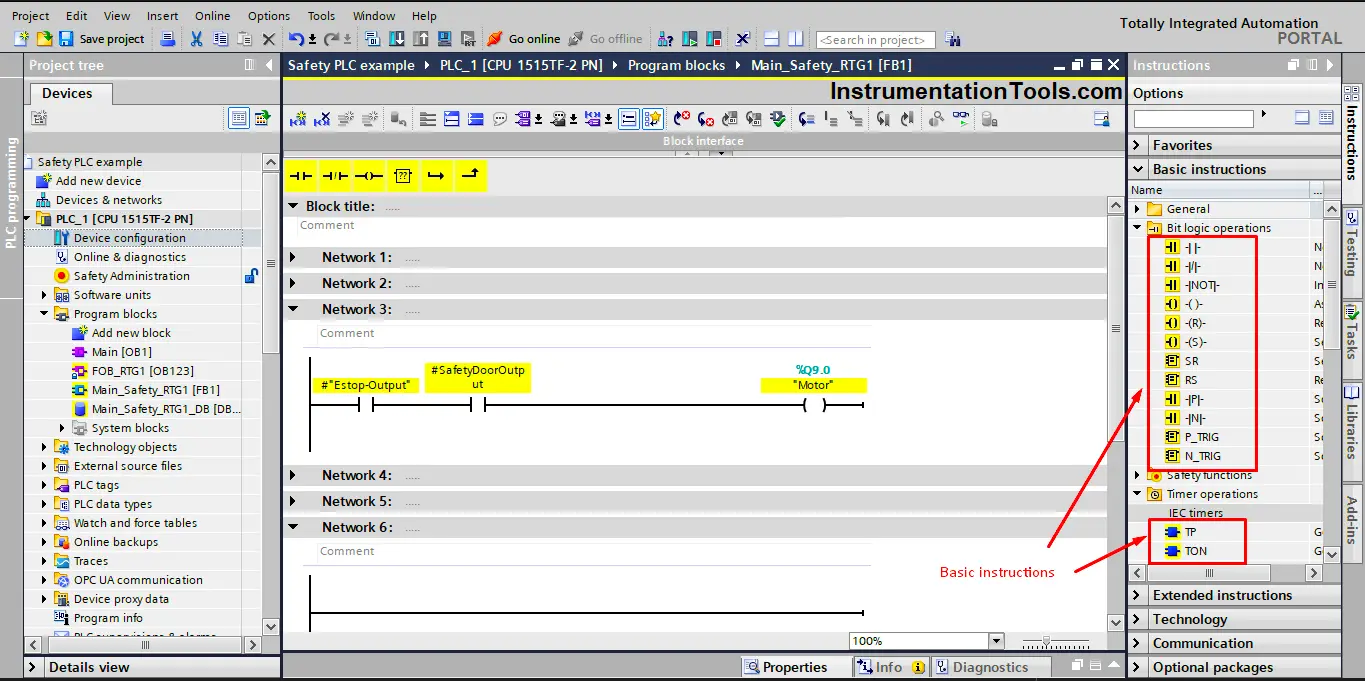
When programming a safety PLC, you can find all instructions available for programming a safety function in LAD or FBD with the configured safety PLC in the “Instructions” task card. See picture 1.
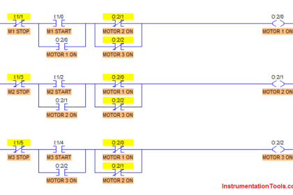
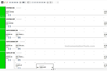
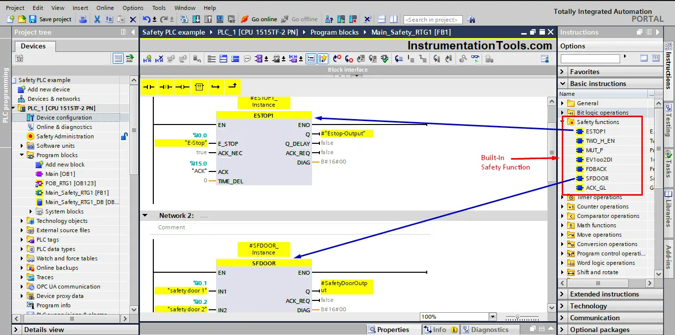
Also, there are special safety functions, like two-hand monitoring, discrepancy analysis,
Muting function, emergency STOP, safety door monitoring, and feedback monitoring that we talked about in previous articles. These built-in functions are already built in such a way that is safe and complies with safety standards. See picture 2.
When programming a safety function for your process, you will most likely be using some of the built-in safety instructions available with the safety PLC and also you will need other basic instructions to complete your logic.
A safety PLC comes with many advantages and built-in features to help ensure safety for your code, but if your programming is sloppy, these features can have negative effects on your code, such as CPU stops and long compilation times.
The following recommendations will help you create optimal code for your process.
These recommendations consider in mind the Siemens S7-1200/s7-1500 safety PLCs with TIA Portal software, but you can use these tips with any other PLC brand.
Recommendations for Safety PLC Hardware Configurations
The following are the best recommendations for safety PLC hardware configuration and selection of equipment.
Select Suitable Safety PLC
To better select your safety plc you should have a clear idea about the following points:
- Required response time of your safety function.
- The number of inputs and outputs required.
- The number of safety modules required.
- Required memory of your code.
These points will help you choose the best CPU for your application.
Keep the Safety Code Cycle Time in your Mind
A long cycle time of your safety program will slow down the response time of your safety functions.
And a short cycle time of your safety program increases the response time of your safety functions but will affect the time for processing the standard user program. So you should design your code with these points in your mind.
Protect your Safety PLC against Unauthorized Access
You should always assign password protection for your safety PLC, to prevent any unauthorized modification to your safety program.
Consistently Upload your Safety PLC Code
Some safety PLCs have the feature of consistently uploading your safety code from automation.
This can help avoid errors and reduce service time and effort.
Safety PLC Programming Best Practices Recommendations
Follow the below-mentioned best practices when writing a Safety PLC program.
Define a Structure for your Safety PLC Logic
Try to divide your program code into separate parts depending on their function like detection, evaluation, or reaction. Or divide your code depending on machine sections.
This will make your code more simple and easy to understand, it will also help reduce programming errors, and make it easier to reuse program parts many times in your code.
Call levels of Safety FCs and Safety FBs
Siemens safety PLCs allows a maximum of eight call levels for your safety program, other brands may allow for more or less, an error will be present if when exceeding this limit and your safety code will not work. Keep that point in mind.
Call Sequence of Blocks
In your safety program, you will have different blocks for different functions like communication between safety modules, logic operation, and evaluation of inputs.
There is a recommended sequence of calling your blocks to ensure the PLC always uses the latest values.
The sequence is as follows:
- Receive information from other CPUs (if there is more than one safety plc in your process).
- Error acknowledgment or reintegration of safety modules
- Evaluation block of the sensors
- Operating mode evaluation
- Logic operations, calculations, evaluations, etc.
- Control blocks for safe actuators
- Send information back to other CPUs (if there is more than one safety plc in your process).
Use Suitable Data Types
Safety PLCs allow the use of UTDs of user data types, it is recommended to structure your tags using these data types so that a change in a PLC data type is automatically updated in all points of use in your safety program.
Use Proper Comments
In the block comment of your block, enter all formal information about the block like; the last block modification, date, and signature, or the functionality of this block. This makes it easier to track functional changes in the block
Use Functional Naming of Variables
In practice, a safety function is described using this terminology: “When a safety door is opened, drive XY must be safely shut down.”
However, safety programs are usually programmed as a release signal, not a shutdown signal. This is due to the fact that safety interconnections are designed based on the closed-circuit principle. If, for example, a safety door is closed, it gives the enable to switch on a safe actuator.
So, it is recommended to Define a uniform name for the variables. That will reflect the meaning and purpose of that variable in your code. For example, SafetyDoorEnable or ConveyorSafetyRelease.
Standardize your Code Blocks
In addition to the logic for evaluating an input safety sensor of logic for controlling an output actuator, some other functionality is often necessary (e.g., edge evaluation, time functions, acknowledgment, etc.)
So, it will be useful to create and reuse modular blocks for sensor evaluation, and controlling actuators.
Create a separate function block for each sensor type (e.g., emergency stop command device, safety door, light curtain, etc.) that combines the evaluation of the sensor and the necessary auxiliary functions. Use this sensor block for other sensors of the same type.
Some of the necessary auxiliary functions may include:
- reset
- restart interlock
- time functions
- edge evaluation
- startup test
Data exchange between standard user program and safety program
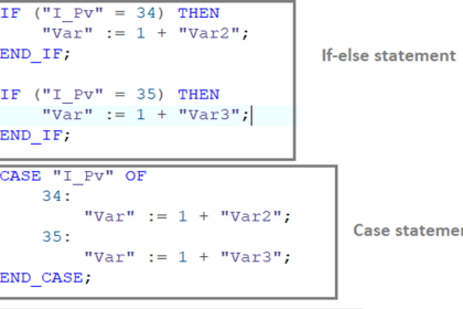
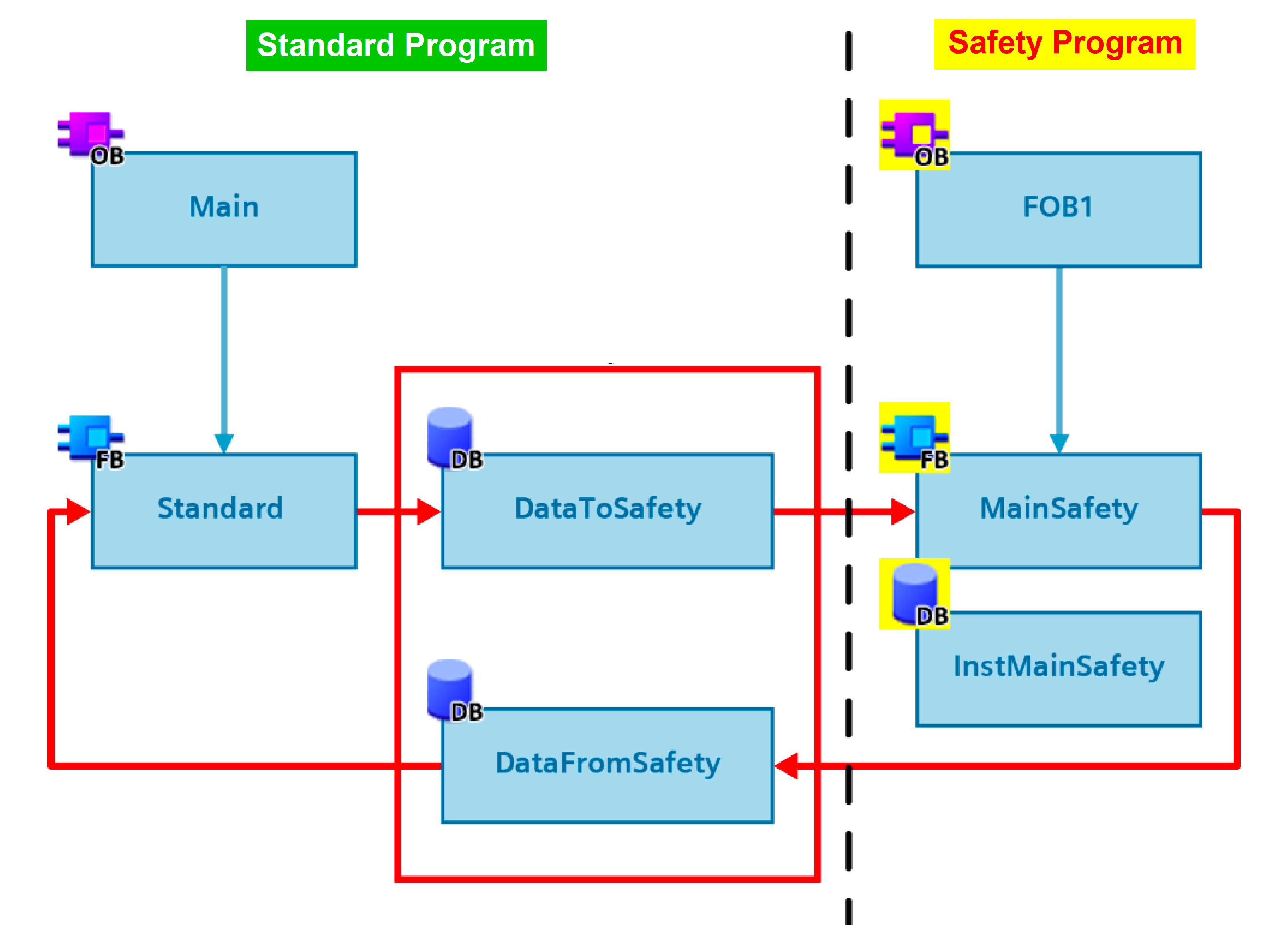
You usually need to transfer data in your code between your safety program and your standard program. In order to move non-safety-related data to the standard user program, you have to define an interface between your safety program and your standard program. Global Data Block is that interface.
It is recommended to define a standard global data block to transfer your data and it is best recommended to make it two separate global data blocks, to separate between data written into the standard program and data read from the standard program. See picture 3.
Prevent Automatic Restarting
If a safety hazard condition is present the safety function should stop your process.
However, your safety program should not allow your process to automatically restart once the safety condition is cleared; instead, the process should wait for a restart signal from the standard program (operator) before restarting the process. See picture 4.
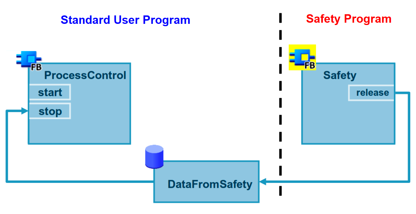
As you can see from picture 4 the process will stop if the release signal from the safety program is interrupted. But the process will only start when the start signal from the Process control function in the standard program is available
Don’t allow automatic Reintegration of safety modules
Automatic reintegration of your safety modules is also not recommended. You can either manually acknowledge all safety modules for reintegration at the same time, using the Global Acknowledgement function which we discussed in a previous article. Or you can manually acknowledge each safety module separately using ACK_REI tags of the respective safety module data blocks:
Conclusions
Previously mentioned PLC recommendations and many others that you can find in programming guidelines’ manuals are presented to help create an optimal program for your process safety.
Not all provided recommendations can be applied at the same time, it will depend on you to decide what to do, based on your process requirements.
Following these PLC tips and recommendations will come with many benefits:
- To be able to reuse standard blocks of your code.
- Easier to review your code, detect errors and perform corrections.
- Your code will be easier to read and understand.
- Reduce the runtime of your safety program.