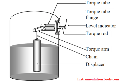
Displacer Level Measurement Calculations
Problem 1 :-
A steel displacer of volume 0.25 cubic feet is 50% immersed in oil of relative density 0.78;
the density of steel = 490 lbs per cubic foot
the density of water = 63 × lbs per cubic foot
Calculate the apparent weight of the displacer.

true weight of displacer = 0.25 × 490 = 122.5 lbs
volume of oil displaced = 0.25 × 0.5 = 0.125 cubic feet
weight of oil displaced = (0.125 × 0.78 × 63) lbs = 6.143 lbs
∴ Apparent weight of displacer = true weight − displaced weight
Apparent weight of displacer = 122.5 − 6.143 lbs = 116.36 lbs
Problem 2 :-
A steel displacer of volume 0.1 cubic feet is to be used as a level sensor in a vessel to store water.
Calculate the following;
1:- the maximum and minimum weights of the displacer.
2:- the maximum range of level able to be sensed, if the diameter of the displ. is 2 inch.

true weight of displacer = 0.1 × 490 lbs = 49 lbs
volume of water displaced = 0.1 cubic feet
weight of water displaced = 0.1 × 63 lbs = 6.3 lbs
∴ min. weight of the displacer = 49 − 6.3 lbs = 42.7 lbs
∴ max. weight of the displacer = 49 lbs
volume of the sensor = πr2L
Note : π = 3.142, 1 in = 1/12 ft = 0.0833ft
volume of the sensor ⇒ 0.1 ft3 = 3.142 × (0.0833)2 × L
0.1 ft3 = 0.0218 × L
hence, the length of displacer, L = 0.1 / 0.0218 = 4.587 ft , or 55 inches
Problem 3 :-
A steel displacer 1 metre long, and volume of 1000 CCs. is to be used to measure the interface level in an oil and water separator. The SG of oil is 0.78, the density of water is 1 kg/litre. Density of steel is 8000 kg per cubic meter.
Find,
1:- the diameter of the displacer.
2:- the displacer weight in air, oil & water.
3:- the “0%” and “100%” weights, if the 50% interface level is set at the displacer’s mid-point, and the span is 0.5 metres.
The displacer is assumed to be totally covered with oil or water.

volume of the sensor = πr2L
1000 c.c.s = 3.142 × r2 × 100 cm
thus, we now have, r2 = 1000 / (3.142 x 100 ) = 3.183 cm2
∴ the radius of displacer, r = Sqrt (3.183) cm = 1.78 cm
hence, the diameter of displacer = 1.78 × 2 cm = 3.56 cm
displacer’s weight in air = density × volume
Note that volume unit has to be inconsistent with density unit 1 ccs = 10−6 m3
= 8000 kgm−3 × (1×103/106) m3 = 8.0 kg
displacer’s weight in oil = (weight in air) − (weight loss in oil)
= 8.0 – (0.5 × 1 × 0.78) kg = 7.61 kg
displacer’s weight in water = (weight in air) − (weight loss in water)
= 8.0 – (0.5 × 1 × 1) kg = 7.50 kg
at 0% interface level, the displacer’s length will be covered 25% with water and 75% with oil. Hence, the displacer’s total weight will be made up of 75% of its weight in oil and 25% weight in water;
∴ displacer weight at 0% = (0.75 × 7.61) + (0.25 × 7.5) = 7.582 kg
at 50%, the displacer’s total weight will be made up of 50% weight in water, and 50% weight in oil;
∴ displacer weight at 50% = (0.5 × 7.61) + (0.5 × 7.5) = 7.555 kg
at 100%, the displacer’s total weight will be made up of 75% weight in water, and 25% weight in oil;
∴ displacer weight at 50% = (0.25 × 7.61) + (0.75 × 7.5) = 7.527 kg
Article Source : N. Asyiddin
Articles You May Like :
Conductive Level Switch Principle
Ultrasonic Level Switch Principle
Level Measurement with wet leg
DP Level Transmitter Calibration


in order to find weight loss in oil and weight loss in water, 0.78×1 and 1×1 are gives density of oil and water respectively. which is multiplied with 0.5. how you got 0.5? volume of oil/water displaced will be equal to the volume of the displacer which is equal to 1000ccc right? (when the displacer is in oil or water completely, the displaced fluid volume will be equivalent to the volume of the displacer. correct me if I’m wrong). instead of 1000ccc(=0.001 m3) how you got 0.5
Dear, 0.5 multiplication due to span of displacer is mentioned 0.5 meter, means only half of displacer length used for level measurement, from 25% water as 0% level to 75% water as 100% level.
& 1000 cc volume equal to 1 litre, so overall multiply by 0.5 liter* density of liquid will give weight loss.
Is this calculations are correct?
I want to calculate the weight of the displacer. I have 3 parameters only height of the displacer, the radius of the displacer, and the material of the displacer the height is 14 inches and the radius is 1.47 inches and the material of the displacer is Carbon steel.
To calculate the displacer weight I used the density of carbon steel which is 0.284 lb/in3 and multiplied it by the volume which is 94.99in^3 and I am getting a weight of 26.94lb is this the correct method to calculate the weight of the displacer? or there is an alternative way to calculate the weight of displacer accurately.
formula used Volume of displacer=pi*r^2*(Height)
Weight=Density*Volume