Inst ToolsInst ToolsInst Tools
  • Courses
  • Automation
    • PLC
    • Control System
    • Safety System
    • Communication
    • Fire & Gas System
  • Instrumentation
    • Design
    • Pressure
    • Temperature
    • Flow
    • Level
    • Vibration
    • Analyzer
    • Control Valve
    • Switch
    • Calibration
    • Erection & Commissioning
  • Interview
    • Instrumentation
    • Electrical
    • Electronics
    • Practical
  • Q&A
    • Instrumentation
    • Control System
    • Electrical
    • Electronics
    • Analog Electronics
    • Digital Electronics
    • Power Electronics
    • Microprocessor
  • Request
Search
  • Books
  • Software
  • Projects
  • Process
  • Tools
  • Basics
  • Formula
  • Power Plant
  • Root Cause Analysis
  • Electrical Basics
  • Animation
  • Standards
  • 4-20 mA Course
  • Siemens PLC Course
Reading: Float Type Level Indicator Principle
Share
Notification Show More
Font ResizerAa
Inst ToolsInst Tools
Font ResizerAa
  • Courses
  • Design
  • PLC
  • Interview
  • Control System
Search
  • Courses
  • Automation
    • PLC
    • Control System
    • Safety System
    • Communication
    • Fire & Gas System
  • Instrumentation
    • Design
    • Pressure
    • Temperature
    • Flow
    • Level
    • Vibration
    • Analyzer
    • Control Valve
    • Switch
    • Calibration
    • Erection & Commissioning
  • Interview
    • Instrumentation
    • Electrical
    • Electronics
    • Practical
  • Q&A
    • Instrumentation
    • Control System
    • Electrical
    • Electronics
    • Analog Electronics
    • Digital Electronics
    • Power Electronics
    • Microprocessor
  • Request
Follow US
All rights reserved. Reproduction in whole or in part without written permission is prohibited.
Inst Tools > Blog > Animation > Float Type Level Indicator Principle

Float Type Level Indicator Principle

Last updated: October 14, 2016 5:56 am
Editorial Staff
Animation Level Measurement
2 Comments
Share
5 Min Read
SHARE

Buoyancy Tape Systems: Level Indicators classified based on buoyancy are

There are two main types of buoyancy tape systems available:

  • Float and tape systems
  • Wire guided float detectors

Float and Tape Systems

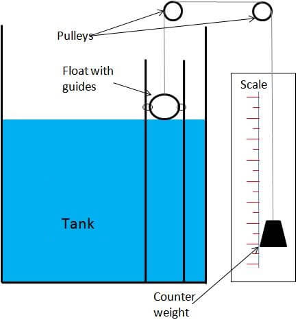
 One common form of level measuring system uses a tape or servo motor which is connected to a float. The height can be read as the float moves with liquid level.

Float devices use the buoyancy of a float to indicate the liquid level in the tank.  One common approach is to attach the float to a chain.  The chain is attached to a counterweight which indicates the level as the float moves up and down.  These types of device are often found on large atmospheric storage tanks.

Float level gauge Principle

Other devices transfer the buoyancy force to a metering device using a torque tube.  The float is connected to the torque tube which twists as the height of the displacement device changes.  The twisting force drives the position of a pointer which then indicates liquid level.

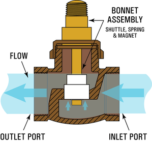
For some applications – where the liquid is corrosive, toxic or in some way hazardous – a magnetic level gauge is used.

The float contains a magnet which changes the orientation of small indicator wafers as it moves up and down.

Float Level Indicator Animation :

Note: This animation only for understanding the concept. In Practical the design may change.

Float Level Gauge Animation

Other systems use the float method by sensing the position of the float magnetically or electrically.

 Float systems can also be used when measuring granular solids as well as liquids.

 Disadvantages 

  • High maintenance
  • Expensive

Wire Guided Float Detectors 

For large level measurements (ie. 20m), wire-guided float detectors can be used. The guide wires are connected to top and bottom anchors and assist in positioning the float as it moves with the fluid level. The tape is connected to the top of the float and runs directly up and over pulleys then down to the gauging head which is outside the tank at a suitable level for viewing. 

The perforated tape is received in the gauge head by a sprocketed counter drive. Any slackness in the tape is taken up by the tape storage reel which is tensioned. Tensioning of the tape storage reel is sufficient to ensure correct measurement, while not affecting the position of the float. 

The shaft on the counter drive rotates as the float moves the perforated tape up and down. The rotary motion of the shaft is used to give a metric readout. 

Float Level Gauge

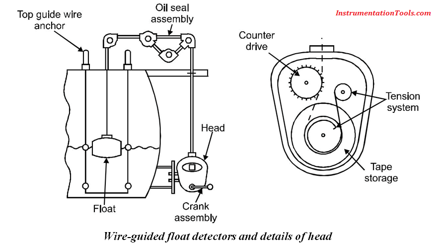
In atmospheric conditions, a seal is used to protect the sensing head from the process fluid. However in pressurised applications, it is better to fill the head with the sensing fluid, particularly if the fluid is clean and lubricating.

Application Limitations

Float and tape systems have a common problem with the tape hanging up. This often occurs if the long guide pipes are not perfectly vertical, where the tape rubs against the inside of the pipes.

Another common problem is with corrosion or dirt, where the tape can be held in place while the float is moving. These problems are more likely to result in a lower than actual reading.

The force from the float weight is usually great enough to overcome the friction of the tape against the impurities, whereas the force of the take-up device may not. Tanks controlled using tape level gauges will often overflow when the tape is stuck.

This problem can be protected against by the use of a separate high level switch.

More advanced controllers are available that monitor tank capacity and pumping rates to check the actual level, rate of change and direction of change.

Summary

One of the main limitations is the high maintenance required in order to keep the tape clean and prevent it from gumming up. This is old technology and is seldom used.

Don't Miss Our Updates
Be the first to get exclusive content straight to your email.
We promise not to spam you. You can unsubscribe at any time.
Invalid email address
You've successfully subscribed !

Continue Reading

Stepper Motor Working Principle
Guided-Wave Radar Instruments Diagnostics
Four Way Solenoid Valve Working Principle
Basics of Level Measurement
Magnetic Level Indicators Working Animation
Resistor Color Code Animation
Share This Article
Facebook Whatsapp Whatsapp LinkedIn Copy Link
Share
2 Comments
  • Agbatutu David says:
    July 6, 2016 at 6:56 pm

    What is the current cost of the float & weight type of level indicator?

    Reply
  • rakesh says:
    October 14, 2016 at 6:02 am

    IOS app pls……………………

    Reply

Leave a Reply Cancel reply

Your email address will not be published. Required fields are marked *

Stay Connected

128.3kFollowersLike
69.1kFollowersFollow
210kSubscribersSubscribe
38kFollowersFollow

Categories

Explore More

Difference between Transparent Level Gauge and Reflex Level Gauge
PID Controller Gains Effect on Manipulated Variable
DP Diaphragm Capillary Seal Level instrument Calibration Procedure
Instruments Tapping Points – Common versus Individual
Ultrasonic Tank Gauging
Pitot Tube Working Principle
Solenoid Valve Working Animation
Radar Level Transmitter in Briddle level Measurement

Keep Learning

RF Level Sensors Principle

RF Level Switches Working Principle

Nuclear Level Measurement

Nuclear Level Detectors Cascade or Master/Slave concept

Level Transmitter with Zero Suppression

DP Level Transmitters Compensation Techniques

Servo Operated Float Level Measurement

Servo Operated Float Level Measurement

Level Gauges

Level Gauge Design

Bubbler Liquid Level Transmitter Calculation

Bubbler Liquid Level Transmitter Calculation

Ultrasonic level measurement

Ultrasonic Level Measurement

DP-Transmitter-with-two-seals

DP Transmitter with Two Seals applications

Learn More

Modern Instrumentation and Control Systems

Migrate From Obsolete to Modern Instrumentation and Control Systems

Contact less Tachometer

Types of Tachometers – Mechanical and Electrical Tachometers

Top 100 Power Plant Engineering Objective Questions & Answers

Top 100 Power Plant Engineering Objective Questions & Answers

Float-type Level Switch for Sensing Low Oil Level

Float-type Level Switch for Sensing Low Oil Level

Pipeline Inspection Tools

Essential Industrial Pipeline Inspection Tools

field-mounted thermocouple

Thermocouple Extension Wires

IoT Interview Questions and Answers

IoT Interview Questions and Answers

Turbine-Compressor System Architecture

Turbine-Compressor System Architecture

Menu

  • About
  • Privacy Policy
  • Copyright

Quick Links

  • Learn PLC
  • Helping Hand
  • Part Time Job

YouTube Subscribe

Follow US
All rights reserved. Reproduction in whole or in part without written permission is prohibited.
Welcome Back!

Sign in to your account

Username or Email Address
Password

Lost your password?