In this article, we will learn 4 methods of calibration procedures of displacer level transmitter (DLT) using water, process fluid, and also interface level measurement.
Instrument Coupling to the Torque Tube
Remove the side cover of the mechanism compartments, and the plug located at the bottom of the instrument.
Required level of 70% liquid for coupling. For level measurements fill water up to 70% of DLT chamber and for interface measurements fill always HSG (High Specific Gravity) liquid up to 70% of DLT chamber.
By looking through the side cover of the mechanism compartments, verify that the screw coupling end of the beam is loose.
Through the 3/4 ” NPT hole at the bottom of the case, press the flexure with your finger to verify it is possible to move the beam from left to right. The value displayed should vary accordingly.
Calibration of Displacer Level Transmitter (DLT)
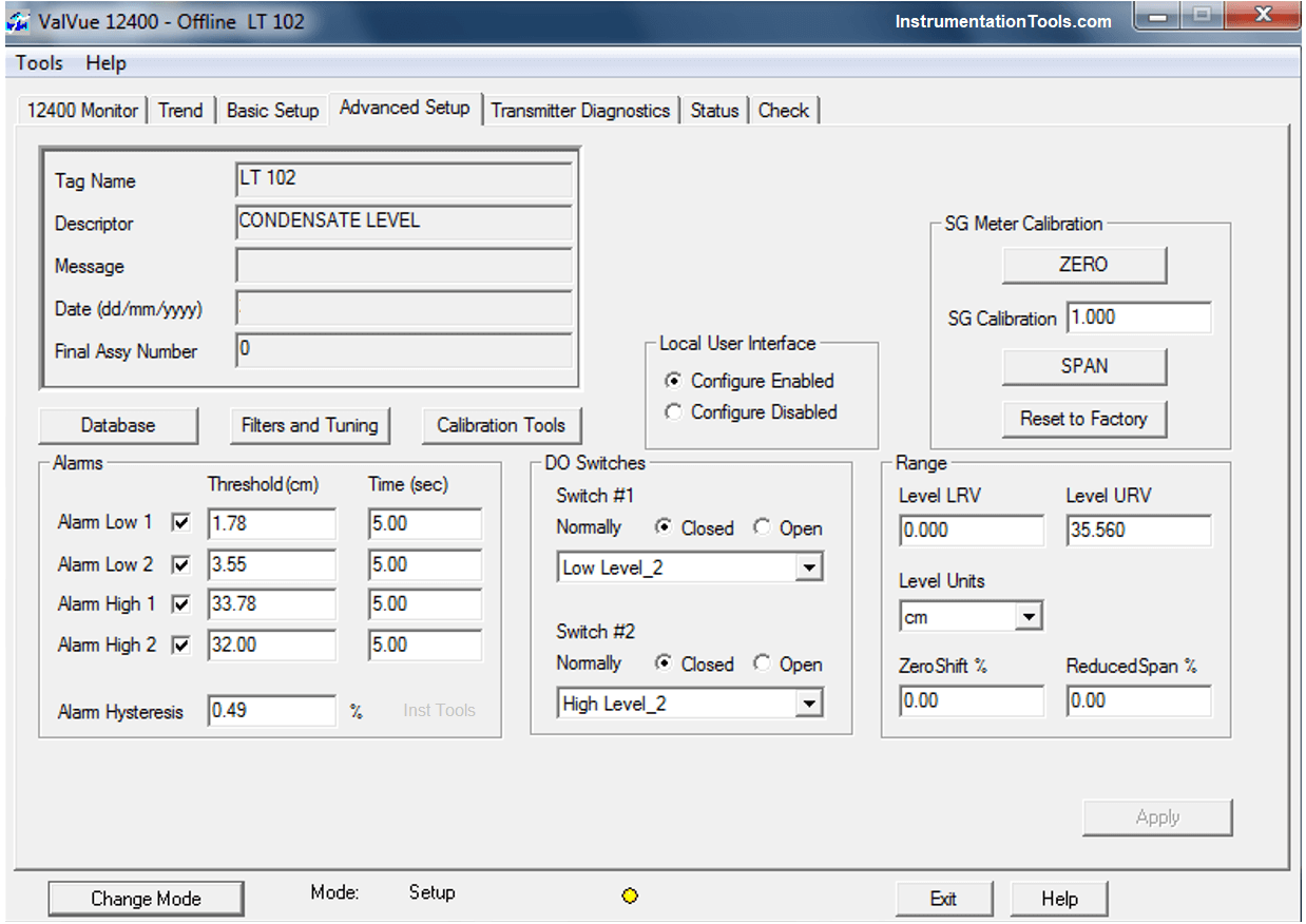
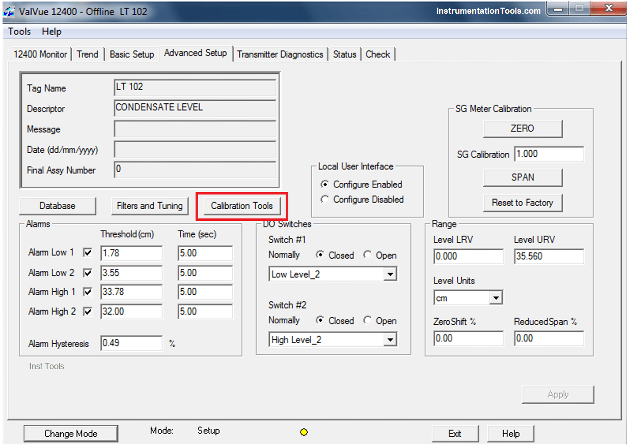
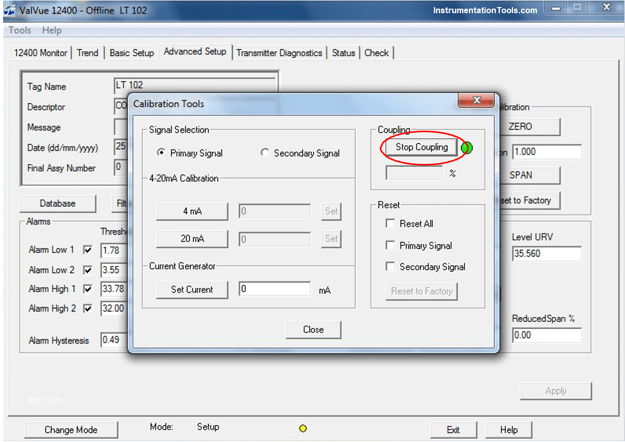
Enter in Advance Setup menu enter calibration tools to display COUPLING method
Enter in Calibration Tools
Enter in Coupling Method to enable. After enabled RED indication shows then adjust flexure to Right or Left to get the value at -5% to +5%.
RED indication turns to GREEN at the value in the Limit.
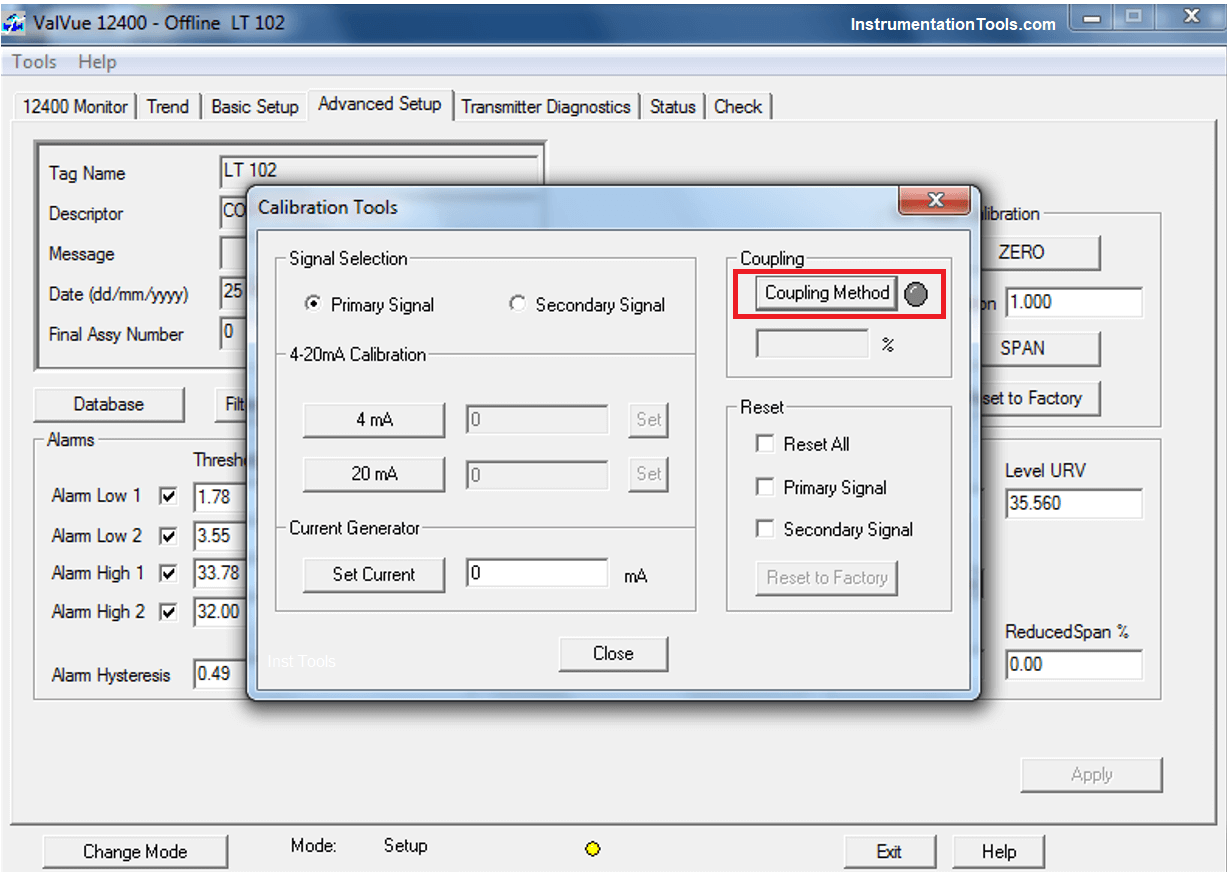
The value read on the LCD must be between –5% and +5%. Getting the value within the limit enter in Stop Coupling.
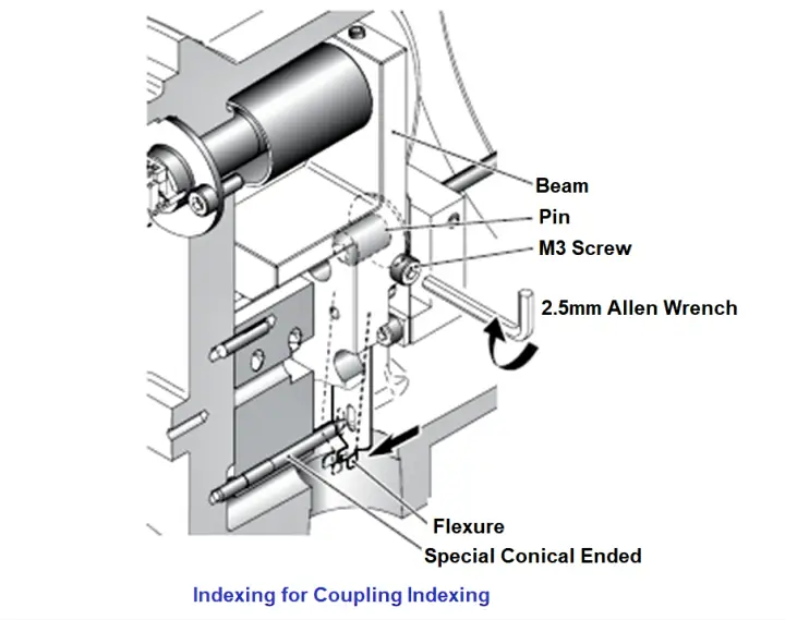
Look at the mechanism compartments through the side cover, and index the oval hole of the flexure towards the special conical ended by bending the flexure toward the case front (see Figure).
The value read on the LCD must be between –5% and +5%. While holding the flexure in that position, slightly but firmly tighten the screw using a 2.5 mm Allen wrench.
NOTE: An undue tightening can damage the instrument.
Calibration Procedure of Displacer Level Transmitter (DLT) for Level Measurement using Water
- Isolation valve of upper & lower nozzle of the DLT is closed.
- Drain & vent valve is opened to remove inventory from the DLT chamber.
- Specific Gravity of the fluid whose level is to be measured is configured in the DLT using HART or Laptop.
- One Flexible transparent tube is connected from drain point of the DLT and hung above upper nozzle of the DLT.
- 100% level is calculated as follow:
- 100% level = SG x CC (Range)
- SG – Specific Gravity of the fluid (Refer datasheet)
- Range/CC – Centre to centre distance between the Upper & Lower Nozzle (Refer datasheet)
- The water is poured until calculated 100% level of the DLT as viewed from the transparent flexible tube. This point is calibrated as SPAN (i.e. 100% value) in the DLT.
- Now the water is drained from drain port of the DLT until ZERO level as viewed from the transparent flexible tube. This point is calibrated as ZERO in the DLT.
- Four equal divisions are marked between 0% & calculated 100% on the DLT chamber and these markings are mentioned as 25%, 50% & 75%.
- Water is poured until 25%, 50% & 75% level of the DLT as viewed from the transparent flexible tube. These levels are verified as 25%, 50% & 75% respectively in the DLT.
- The DLT is now calibrated and then it is taken online by closing vent & drain valve and opening isolation valve of the lower flange and then upper flange.
Calibration Procedure for Interface Level Measurement using Water
- Isolation valve of upper & lower nozzle of the DLT is closed.
- Drain & vent valve is opened to remove inventory from the DLT chamber.
- One Flexible transparent tube is connected from drain point of the DLT and hung above upper nozzle of the DLT.
- Specific Gravity of the process fluids whose interface level is to be measured is configured in the DLT using HART or Laptop.
- 100% level is calculated as follow:
- 100% level = HSG x CC (Range)
- HSG – Specific Gravity of Heavier fluid
- CC – Centre to centre distance between the Upper & Lower Nozzle.
- 0% level is calculated as follow:
- 0% level = LSG x CC (Range)
- SGL – Specific Gravity of lighter fluid (Refer datasheet)
- Range/CC – Centre to centre distance between the Upper & Lower Nozzle (Refer datasheet)
- The water is poured until calculated 100% level of the DLT as viewed from the transparent flexible tube. This point is calibrated as SPAN (i.e. 100% value) in the DLT.
- Now the water is drained from drain port of the DLT until calculated 0% level as viewed from the transparent flexible tube. This point is calibrated as ZERO in the DLT.
- Four equal divisions are marked between calculated 0% & calculated 100% on the DLT chamber and these markings are mentioned as 25%, 50% & 75%.
- Water is poured until 25%, 50% & 75% level of the DLT as viewed from the transparent flexible tube. These levels are verified as 25%, 50% & 75% respectively in the DLT.
- The DLT is now calibrated and then it is taken online by closing vent & drain valve and opening isolation valve of the lower flange and then upper flange.
Calibration Procedure for Level Measurement using Process Fluid
- Isolation valve of upper & lower nozzle of the DLT is closed.
- Drain & vent valve is opened to remove inventory from the DLT chamber.
- Specific Gravity of the process fluid whose level is to be measured is configured in the DLT using HART or Laptop.
- One Flexible transparent tube is connected from drain point of the DLT and hung above upper nozzle of the DLT.
- Process fluid is poured until 100% level of the DLT as viewed from the transparent flexible tube. This point is calibrated as SPAN (i.e. 100% value) in the DLT.
- Then the process Fluid is drained from drain port of the DLT until ZERO level as viewed from the transparent flexible tube. This point is calibrated as ZERO in the DLT.
- Four equal divisions are marked between 0% & 100% on the DLT chamber and these markings are mentioned as 25%, 50% & 75%.
- Process fluid is poured until 25%, 50% & 75% level of the DLT as viewed from the transparent flexible tube. These levels are verified as 25%, 50% & 75% respectively in the DLT.
- The DLT is now calibrated and then it is taken online by closing vent & drain valve and opening isolation valve of the lower flange and then upper flange.
Calibration Procedure for Interface Level Measurement using with Water and Process Fluid
- Isolation valve of upper & lower nozzle of the DLT is closed.
- Drain & vent valve is opened to remove inventory from the DLT chamber.
- One Flexible transparent tube is connected from drain point of the DLT and hung above upper nozzle of the DLT.
- Specific Gravity of the process fluids whose interface level is to be measured is configured in the DLT using HART or Laptop.
- Lighter Process Fluid (LSG) is poured from vent port of the DLT until 100% level as viewed from the transparent flexible tube. This point is calibrated as ZERO in the DLT.
- Heavier Process Fluid (HSG) is poured from vent port of the DLT until 100% level as viewed from the transparent flexible tube. This point is calibrated as SPAN (i.e. 100%) in the DLT.
- Four equal divisions are marked between 0% & 100% on the DLT chamber and these markings are mentioned as 25%, 50% & 75%.
- Process fluid (i.e. combined heavier & lighter fluid) is poured until interphase of these fluid reaches 25%, 50% & 75% level of the DLT as viewed from the transparent flexible tube. These levels are verified as 25%, 50% & 75% respectively in the DLT.
- The DLT is now calibrated and then it is taken online by closing vent & drain valve and opening isolation valve of the lower flange and then upper flange.
Credits: PLQP Instrumentation Team
If you liked this article, then please subscribe to our YouTube Channel for Instrumentation, Electrical, PLC, and SCADA video tutorials.
You can also follow us on Facebook and Twitter to receive daily updates.
Read Next:


hello,
we have installed magnetrol e3 displacer level transmitter as well as an interface transmitter.
level transmitter is showing “loop current saturated” and system side we have Schneider DCS latest when simulation from the field is done the IO bad alarm is coming and when we increase the current from 4,8,12,16 & 20 mA in the display it’s reading correctly and system side it’s not measuring but same time raw count is increasing respectively.
note: when calibration is done with water it’s working fine.
in interface level transmitter it’s showing below alerts,
initializing
secondary fault lo
loop current fixed
more status available
device malfunction.
kindly provide the solution for the above query.
thank you
Please check both isolation valves of displacer chamber are open. Drain valves closed.