Today we are going to discuss another interesting topic related to one function provided in the transmitter which plays a very important role in saving plant/equipment.
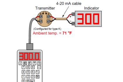
The role of the transmitter is a very basic one. It receives the input from a sensor and converts it into system understandable values i.e. it can be a 4-20 mA signal or FF signal or any other kind of signal depending on the instrument type.
For configuring this transmitter various parameters are to be configured during the commissioning of the transmitter like Device tag, Primary variable, Secondary variable, Tertiary variable, Range of all variables, LRV, URV, Engineering units, Damping, Transfer function (Linear/Square root), Display setting, and one very important parameter in temperature transmitter i.e. Burnout Function.
Burnout Function in Temperature Transmitter
Have you ever thought about what happens when RTD or thermocouple fails?
Let me create one scenario. Suppose in the field, say RTD fails due to some reason and the resistance becomes too high (open connection) then the process will trip if there is an interlock on high temperature. Due to this trip, the plant shutdown may happen and a production loss would have occurred.
Think of another scenario where RTD fails and becomes a short circuit. For the PT100 RTD sensor, when resistance becomes zero then the equivalent temperature is -242.021 °C. But in real-time, Say the temperature is increasing in the plant and if it is crossed above the critical temperature value, the blast may occur, in that case, an incident may happen.
Now to overcome these issues, the burnout function needs to be implemented.
In burnout function, whenever a transmitter detects sensor failure (it may be a short circuit or open circuit), a defined current signal which is pre-configured in the transmitter is transmitted. We can configure a low value, high value, or some other defined value or last state (in a 4-20mA loop, high is 20 mA and low is 4 mA) as per our requirement.
Now the main question is how will the transmitter detect that the actual sensor has failed because some spurious readings also can create such a scenario.
So as per NAMUR NE 43 “When the loop current is below 3.6 mA or above 21 mA this is interpreted as a sensor fault. In order to avoid false alarms, the signal shall be present for at least 4 seconds before it is interpreted as sensor fault”
Now what setting needs to be implemented in the transmitter burnout function is to be decided by looking at the process.
One very important thing to be noted here is that whenever the burnout function is configured in the transmitter, then it should be clearly mentioned somewhere (written in the field or a list of such transmitters should be made) so that whenever an instrumentation technician/engineer goes for any activity on that transmitter, the necessary bypass has been done in the DCS or ESD system.
In some transmitters, burnout is also applied if the transmitter senses internal circuit failures.