Radar level instruments measure the distance from the transmitter (located at some high point) to the surface of a process material located farther below in much the same way as ultrasonic transmitters – by measuring the time-of-flight of a traveling wave.
The fundamental difference between a radar instrument and an ultrasonic instrument is the type of wave used: radio waves instead of sound waves.
Radio waves are electromagnetic in nature (comprised of alternating electric and magnetic fields), and very high frequency (in the microwave frequency range – GHz).
Sound waves are mechanical vibrations (transmitted from molecule to molecule in a fluid or solid substance) and of much lower frequency (tens or hundreds of kilohertz – still too high for a human being to detect as a tone) than radio waves.
Some radar level instruments use waveguide “probes” to guide the electromagnetic waves to and from the process liquid while others send electromagnetic waves out through open space to reflect off the process material.
The instruments using waveguides are called guided-wave radar instruments, whereas the radar instruments relying on open space for signal propagation are called non-contact radar.
Radar Level Measurement
The differences between these two varieties of radar instruments is shown in the following illustration:

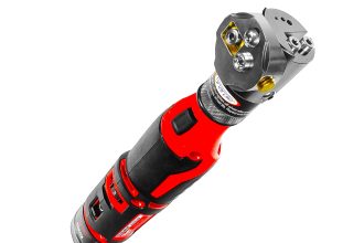
Photographs of non-contact (left) and guided-wave (right) radar level transmitters are shown below.
The non-contact transmitter is placed on a table for inspection while the guided-wave transmitter is installed in a “cage” similar to that of a displacement-style level transmitter attached to the vessel by two pipes:
Also See : Guided-wave Radar Level Measurement Animation
Non-contact radar devices suffer much more signal loss than guided-wave radar devices, due to the natural tendency of electromagnetic radiation to disperse over space. Waveguides combat this signal loss by channeling the radio energy along a straight-line path.
Probes used in guided-wave radar instruments may be single metal rods, parallel pairs of metal rods, or a coaxial metal rod and- tube structure.
Single-rod probes suffer the greatest energy losses, while coaxial probes excel at guiding the microwave energy to the liquid interface and back.
However, single-rod probes are much more tolerant of process fouling than two-rod or (especially) coaxial probes, where sticky masses of viscous liquid and/or solid matter cling to the probe.
Such fouling deposits, if severe enough, will cause electromagnetic wave reflections that “look” to the transmitter like the reflection from an actual liquid level or interface.

Non-contact radar devices suffer much more signal loss than guided-wave radar devices, due to the natural tendency of electromagnetic radiation to disperse over space.
Waveguides combat this signal loss by channeling the radio energy along a straight-line path. Probes used in guided-wave radar instruments may be single metal rods, parallel pairs of metal rods, or a coaxial metal rod and- tube structure.
Single-rod probes suffer the greatest energy losses, while coaxial probes excel at guiding the microwave energy to the liquid interface and back.
However, single-rod probes are much more tolerant of process fouling than two-rod or (especially) coaxial probes, where sticky masses of viscous liquid and/or solid matter cling to the probe.
Such fouling deposits, if severe enough, will cause electromagnetic wave reflections that “look” to the transmitter like the reflection from an actual liquid level or interface.
Non-contact radar instruments rely on antennas to direct microwave energy into the vessel, and to receive the echo (return) energy.
These antennas must be kept clean and dry, which may be a problem if the liquid being measured emits condensable vapors.
For this reason, non-contact radar instruments are often separated from the vessel interior by means of a dielectric window (made of some substance such as plastic that is relatively “transparent” to electromagnetic waves yet acts as an effective vapor barrier):

Electromagnetic waves travel at the speed of light 2.9979 × 10⁸ meters per second in a perfect vacuum. The velocity of an electromagnetic wave through space depends on the dielectric permittivity (symbolized by the Greek letter “epsilon,” ∈) of that space.
A formula relating wave velocity (v) to relative permittivity (the ratio of a substance’s permittivity to that of a perfect vacuum, symbolized as ǫr and sometimes called the dielectric constant of the substance) and the speed of light in a perfect vacuum (c) is shown here:

As mentioned previously, the calibration of any echo-based level transmitter depends on knowing the speed of wave propagation through the medium separating the instrument from the process fluid interface.
For radar transmitters sensing a single liquid below a gas or vapor, this speed is the speed of light through that gas or vapor space, which we know to be a function of electrical permittivity.
The relative permittivity of air at standard pressure and temperature is very nearly unity (1). This means the speed of light in air under atmospheric pressure and ambient temperature will very nearly be the same as it is for a perfect vacuum (2.9979 × 10⁸ meters per second).
If, however, the vapor space above the liquid is not ambient air, and is subject to large changes in temperature and/or pressure which cause the vapor’s density to change, the permittivity of that vapor may substantially change and consequently skew the speed of light, and therefore the calibration of the level instrument. This calibration shift is sometimes referred to as the gas phase effect.
A formula useful for calculating the permittivity of any gas or vapor based on both pressure and temperature is shown here:

Where,
∈r = Relative permittivity of a gas at a given pressure (P) and temperature (T)
∈ref = Relative permittivity of the same gas at standard pressure (Pref ) and temperature (Tref )
P = Absolute pressure of gas (bars)
Pref = Absolute pressure of gas under standard conditions (≈ 1 bar)
T = Absolute temperature of gas (Kelvin)
Tref = Absolute temperature of gas under standard conditions (≈ 273 K)
This formula is based on the principle that bulk permittivity is a function of density. We may see why this is by running a “thought experiment” in which a sample of gas becomes denser.
As gas density increases, more gas molecules will become packed into the same volume of space.
If each gas molecule’s permittivity is greater than the permittivity of empty space, then having more of those gas molecules present will mean the permittivity of that volume increases.
Greater permittivity, of course, decreases the velocity of light through the gas, and thereby affects the calibration of the radar instrument.
Relating this concept to pressure and temperature variations in the gas, we can see that the permittivity of a gas increases with increasing pressure (by increasing gas density), and decreases with increasing temperature (by decreasing gas density).
This means the speed of light through a gas decreases with increasing pressure, and increases with increasing temperature.
For radar level instruments operating in gas environments subject to significant pressure and temperature (i.e. density) variations, the consequent variations in the speed of light through that gas will compromise the instrument’s accuracy.
With ultrasonic level instruments, the necessary condition for an echo to occur is that the sound wave encounters a sudden change in material density.
With radar level instruments, the necessary condition for wave reflection is a sudden change in dielectric permittivity (∈). When an electromagnetic wave encounters a sudden change in dielectric permittivity, some of that wave’s energy will be reflected in the form of another wave traveling the opposite direction, while the balance of the wave’s energy continues forward to propagate into the new material.
The strength of the reflected signal depends on how greatly the two materials’ permittivities differ:

This same principle explains reflected signals in copper transmission lines as well. Any discontinuities (sudden changes in characteristic impedance) along the length of a transmission line will reflect a portion of the electrical signal’s power back to the source.
In a transmission line, continuities may be formed by pinches, breaks, or short-circuits. In a radar level measurement system, any sudden change in electrical permittivity is a discontinuity that reflects some of the incident wave energy back to the source.
Thus, radar level instruments function best when there is a large difference in permittivity between the two substances at the interface.
As shown in the previous illustration, air and water meet this criterion, having an 80:1 permittivity ratio.
The ratio of reflected power to incident (transmitted) power at any interface of materials is called the power reflection factor (R).
This may be expressed as a unitless ratio, or more often as a decibel figure. The relationship between dielectric permittivity and reflection factor is as follows:

Where,
R = Power reflection factor at interface, as a unitless ratio
∈r1 = Relative permittivity (dielectric constant) of the first medium,
∈r2 = Relative permittivity (dielectric constant) of the second medium
The fraction of incident power transmitted through the interface (Pforward/Pincident ) is, of course, the mathematical complement of the power reflection factor: 1 − R.
For situations where the first medium is air or some other low-permittivity gas, the formula simplifies to the following form (with ∈r being the relative permittivity of the reflecting substance):

In the previous illustration, the two media were air (∈r ≈ 1) and water (∈r ≈ 80) – a nearly ideal scenario for strong signal reflection. Given these relative permittivity values, the power reflection factor has a value of 0.638 (63.8%), or −1.95 dB.
This means well over half the incident power reflects off the air/water interface to form a strong echo signal, with the remaining 0.362 (36.2%) of the wave’s power traveling through the air-water interface and propagating into water.
If the liquid in question is gasoline rather than water (having a rather low relative permittivity value of approximately 2), the power reflection ratio will only be 0.0294 (2.94%) or −15.3 dB, with the vast majority of the wave’s power successfully penetrating the air-gasoline interface.
The longer version of the power reflection factor formula suggests liquid-liquid interfaces should be detectable using radar, and indeed they are.
All that is needed is a sufficiently large difference in permittivity between the two liquids to create a strong enough echo to reliably detect. Liquid-liquid interface level measurement with radar works best when the upper liquid has a substantially lesser permittivity value than the lower liquid.
A layer of hydrocarbon oil on top of water (or any aqueous solution such as an acid or a caustic) is a good candidate for guided-wave radar level measurement.
An example of a liquid-liquid interface that would be very difficult for a radar instrument to detect is water (∈r ≈ 80) above glycerin (∈r ≈ 42).
If the radar instrument uses a digital network protocol to communicate information with a host system (such as HART or any number of “fieldbus” standards), it may perform as a multi-variable transmitter, transmitting both the interface level measurement and the total liquid level measurement simultaneously.
This capability is rather unique to guided-wave radar transmitters, and is very useful in some processes because it eliminates the need for multiple instruments measuring multiple levels.
One reason why a lesser-∈ fluid above a greater-∈ fluid is easier to detect than the inverse is due to the necessity of the signal having to travel through a gas-liquid interface above the liquid-liquid interface.
With gases and vapors having such small ǫ values, the signal would have to pass through the gas-liquid interface first in order to reach the liquid-liquid interface.
This gas-liquid interface, having the greatest difference in ǫ values of any interface within the vessel, will be most reflective to electromagnetic energy in both directions.
Thus, only a small portion of the incident wave will ever reach the liquid-liquid interface, and a similarly small portion of the wave reflected off the liquid-liquid interface (which itself is a fraction of the forward wave power that made it through the gas-liquid interface on its way down) will ever make it through the gas-liquid interface on its way back up to the instrument.
The situation is much improved if the ǫ values of the two liquid layers are inverted, as shown in this hypothetical comparison (all calculations assume no power dissipation along the way, only reflection at the interfaces):

As you can see in the illustration, the difference in power received back at the instrument is nearly two to one, just from the upper liquid having the lesser of two identical ǫ values.
Of course, in real life you do not have the luxury of choosing which liquid will go on top of the other (this being determined by fluid density), but you do have the luxury of choosing the appropriate liquid-liquid interface level measurement technology, and as you can see here certain orientations of ǫ values are less detectable with radar than others.
Another factor working against radar as a liquid-liquid interface measurement technology for interfaces where the upper liquid has a greater dielectric constant is that fact that many high-∈ liquids are aqueous in nature, and water readily dissipates microwave energy.
This fact is exploited in microwave ovens, where microwave radiation excites water molecules in the food, dissipating energy in the form of heat.
For a radar-based level measurement system consisting of gas/vapor over water over some other (heavier) liquid, the echo signal will be extremely weak because the signal must pass through the “lossy” water layer twice before it returns to the radar instrument.
Also See : Level Transmitters Animation
Electromagnetic energy losses are important to consider in radar level instrumentation, even when the detected interface is simply gas (or vapor) over liquid.
The power reflection factor formula only predicts the ratio of reflected power to incident power at an interface of substances. Just because an air-water interface reflects 63.8% of the incident power does not mean 63.8% of the incident power will actually return to the transceiver antenna!
Any dissipative losses between the transceiver and the interface(s) of concern will weaken the signal, to the point where it may become difficult to distinguish from noise.
Another important factor in maximizing reflected power is the degree to which the microwaves disperse on their way to the liquid interface(s) and back to the transceiver.
Guided-wave radar instruments receive a far greater percentage of their transmitted power than non-contact radar instruments because the metal probe used to guide the microwave signal pulses help prevent the waves from spreading (and therefore weakening) throughout the liquids as they propagate.
In other words, the probe functions as a transmission line to direct and focus the microwave energy, ensuring a straight path from the instrument into the liquid, and a straight echo return path from the liquid back to the instrument. This is why guided-wave radar is the only practical radar technology for measuring liquid-liquid interfaces.
A critically important factor in accurate level measurement using radar instruments is that the dielectric permittivity of every substance lying between the radar instrument and the interface of interest be accurately known.
The reason for this is rooted in the dependence of electromagnetic wave propagation velocity to relative permittivity. Recalling the wave velocity formula shown earlier:

Where,
v = Velocity of electromagnetic wave through a particular substance
c = Speed of light in a perfect vacuum (≈ 3 × 10⁸ meters per second)
∈r = Relative permittivity (dielectric constant) of the substance
In the case of a single-liquid application where nothing but gas or vapor exists above the liquid, the permittivity of that gas or vapor must be precisely known.
In the case of a two-liquid interface with gas or vapor above, the relative permittivities of both gas and upper liquids must be accurately known in order to accurately measure the liquid-liquid interface.
Changes in dielectric constant value of the medium or media through which the microwaves must travel and echo will cause the microwave radiation to propagate at different velocities.
Since all radar measurement is based on time-of-flight through the media separating the radar transceiver from the echo interface, changes in wave velocity through this media will affect the amount of time required for the wave to travel from the transceiver to the echo interface, and reflect back to the transceiver.
Therefore, changes in dielectric constant are relevant to the accuracy of any radar level measurement.
Factors influencing the dielectric constant of gases include pressure and temperature, which means the accuracy of a radar level instrument will vary as gas pressure and/or gas temperature vary!
This is often referred to as the gas phase effect. Whether or not this variation is substantial enough to consider for any application depends on the desired measurement accuracy and the degree of permittivity change from one pressure/temperature extreme to another.
In no case should a radar instrument be considered for any level measurement application unless the dielectric constant value(s) of the upper media are precisely known.
This is analogous to the dependence on liquid density that hydrostatic level instruments face. It is futile to attempt level measurement based on hydrostatic pressure if liquid density is unknown or widely varying, and it is just as futile to attempt level measurement based on radar if the dielectric constants are unknown or varies widely.
One way to compensate for the gas phase effect in radar level instruments is to equip the instrument with a reference probe of fixed length oriented in such a way that its entire length is always above the liquid level (i.e. it only senses gas).
If the permittivity of the gas is constant, the echo time along this reference probe will remain the same.
If, however, the gas permittivity changes, the reference probe’s echo time will correspondingly change, allowing the instrument’s microprocessor to measure gas permittivity and consequently adjust calculations for liquid level based on this known change.
This concept is analogous to the compensating probe sometimes used in capacitive level sensors, designed to measure fluid permittivity so as to compensate for any changes in this critical parameter.
As with ultrasonic level instruments, radar level instruments can sense the level of solid substances in vessels (e.g. powders and granules) and not just liquids.
The same caveat of repose angle applicable to ultrasonic level measurement, however, is a factor for radar measurement as well.
Also, low particulate solid density (i.e. significant amounts of air between the solid particles) tends to reduce the material’s dielectric constant and thereby weaken the radar echo.
Credits : Tony R. Kuphaldt – Creative Commons Attribution 4.0 License


What difference between guide wave radar & non guide wave radar.
Measure the tank with steam. Can I use a radar level sensor?